Hybrid solid mesh structure for electron beam melting customized implant to treat bone cancer
- PMID: 37323484
- PMCID: PMC10261134
- DOI: 10.18063/ijb.716
Hybrid solid mesh structure for electron beam melting customized implant to treat bone cancer
Abstract
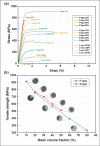
15Bone replacement implants manufactured by electron beam melting have been widely studied for use in bone tumor treatment. In this application, a hybrid structure implant with a combination of solid and lattice structures guarantees strong adhesion between bone and soft tissues. This hybrid implant must exhibit adequate mechanical performance so as to satisfy the safety criteria considering repeated weight loading during the patient's lifetime. With a low volume of a clinical case, various shape and volume combinations, including both solid and lattice structures, should be evaluated to provide guidelines for implant design. This study examined the mechanical performance of the hybrid lattice by investigating two shapes of the hybrid implant and volume fractions of the solid and lattice structures, along with microstructural, mechanical, and computational analyses. These results demonstrate how hybrid implants may be designed to improve clinical outcomes by using patient-specific orthopedic implants with optimized volume fraction of the lattice structure, allowing for effective enhancement of mechanical performance as well as optimized design for bone cell ingrowth.
Keywords: 3D printing; Bone cancer; Electron beam melting; Fracture analysis; Titanium alloy implant.
Copyright: © 2023 Park JW, Seo E, Park H, et al.
Conflict of interest statement
The authors declare that they have no known competing financial interests or personal relationships that could have appeared to influence the work reported in this paper.
Figures


References
-
- Mankin H, Gebhardt M, Jennings L, et al. Long-term results of allograft replacement in the management of bone tumors. Relat Res. 1996;324:86–97. - PubMed
-
- Wunder J, Leitch K, Griffin A, et al. Comparison of two methods of reconstruction for primary malignant tumors at the knee: A sequential cohort study. J Surg Oncol. 2001;77:89–99. https://doi.org/10.1002/jso.1076. - PubMed
-
- Jeon DG, Kim MS, Cho WH, et al. Pasteurized autograft for intercalary reconstruction. Clin Orthop Relat Res. 2007;456:203–210. https://doi.org/10.1097/BLO.0b013e31802e7ec8. - PubMed
-
- Jeon DG, Song WS, Cho WH, et al. Overlapping allograft for primary or salvage bone tumor reconstruction. J Surg Oncol. 2014;110:366–371. https://doi.org/10.1002/jso.23669. - PubMed
-
- Shusteff M, Browar AEM, Kelly EW, et al. One-step volumetric additive manufacturing of complex polymer structures. Sci Adv. 2017;3:eaao5496. https://doi.org/10.1126/sciadv.aao5496. - PMC - PubMed
LinkOut - more resources
Full Text Sources
