Review
. 2023 May 22;5(12):3177-3208.
doi: 10.1039/d3na00010a. eCollection 2023 Jun 13.

Accounts of applied molecular rotors and rotary motors: recent advances

Affiliations
Review

Accounts of applied molecular rotors and rotary motors: recent advances

Anup Singhania et al. Nanoscale Adv. .

Abstract

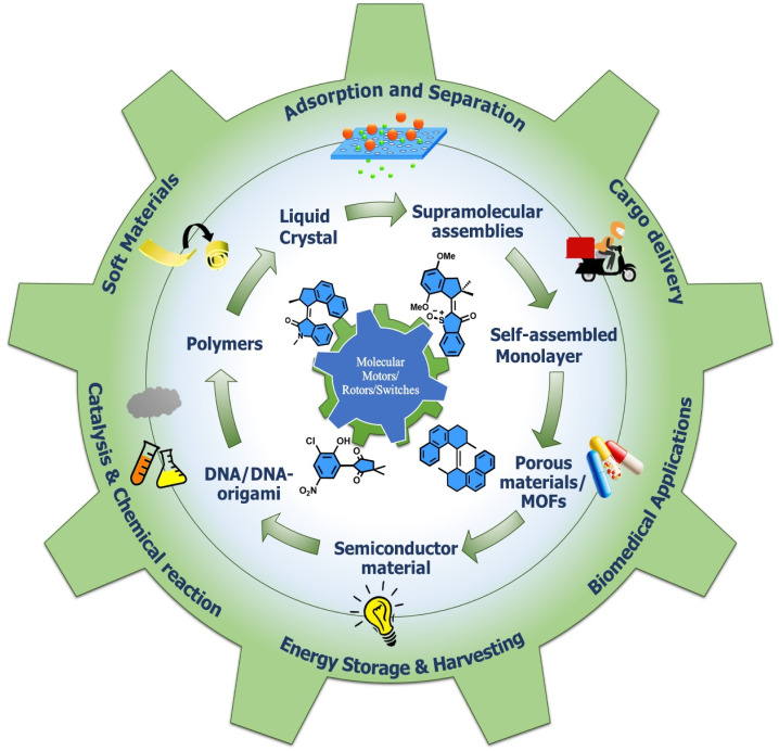
Molecular machines are nanoscale devices capable of performing mechanical works at molecular level. These systems could be a single molecule or a collection of component molecules that interrelate with one another to produce nanomechanical movements and resulting performances. The design of the components of molecular machine with bioinspired traits results in various nanomechanical motions. Some known molecular machines are rotors, motors, nanocars, gears, elevators, and so on based on their nanomechanical motion. The conversion of these individual nanomechanical motions to collective motions via integration into suitable platforms yields impressive macroscopic output at varied sizes. Instead of limited experimental acquaintances, the researchers demonstrated several applications of molecular machines in chemical transformation, energy conversion, gas/liquid separation, biomedical use, and soft material fabrication. As a result, the development of new molecular machines and their applications has accelerated over the previous two decades. This review highlights the design principles and application scopes of several rotors and rotary motor systems because these machines are used in real applications. This review also offers a systematic and thorough overview of current advancements in rotary motors, providing in-depth knowledge and predicting future problems and goals in this area.


Conflict of interest statement

The authors declare there are no conflicts of interest.

Figures

Chart 1
Chart 1. An initial image of molecular rotors/motors and their respective applications.
Fig. 1
Fig. 1. Graphical representation of (a) a macroscopic task with an example of the movement of a brick and (b) a microscopic brick information ratchet. (c) A cyclic four-state mechanism for the Brownian machine is shown (where W = white, B = black, S = substrate, P = product, and L implies motor bound to S and P) Kb and Kf are equilibrium constants between the black and white stairs. Reproduced with permission. Copyright 2019, The Authors, Published by Springer Nature. (d) Mechanisms of Power stroke (i) elastic relaxation. A fuel processing event (e.g., binding of an ATP or releasing a hydrolysis product, denoted by a lightning symbol): leads to the release of elastic energy. (ii) Conformational transition. Due to the conformational change of the motor, a fuel-processing event leads to a variation in the mechanical element's equilibrium position (denoted by the swinging rod). Before and after the stroke, the motor is not strained; Brownian ratchet: (iii) BR follows the flashing ratchet model; the potential V(x) barrier could change externally by supplying energy and generating a net current. (iv) Rectified diffusion model (based on the concept of information ratchet). Reproduced with permission. Copyright 2019, National Academy of Sciences. (e) A power-harvesting double ratchet motor: fusion of power stroke and Brownian ratchet. Adapted with permission from ref. . Copyright 2023, American Chemical Society.
Fig. 2
Fig. 2. (a) First light-activated rotary motor. (b) Full 360° rotational cycle of oxindole-based molecular motor. (c) The four-step rotary motion of the phosphine-based molecular motor under photochemical conditions shows a three-step rotary cycle at elevated temperature. (d) Cyclic representation of the isomerization process of the imine rotor that undergoes an EZ transition state.
Fig. 3
Fig. 3. (a) Molecular structures of hemithioindigo motor with four stable diastereoisomers and their cyclic motion. The “rotors” are colored green. (b) Structure and mechanism of directional rotation in the chemically-fueled motor.
Fig. 4
Fig. 4. Approaches for controlling the dynamic motions in molecular motors. (a) Allosteric regulation of the overcrowded alkene-based motor by incorporating Zn, Pd, and Pt metal chlorides under light. (b) Schematic representation of a multistage modulated rotor, in which the four dynamic stages of the rotors are achieved with acid–base and allosteric interaction. Reproduced with permission. Copyright 2018, The Authors, published by Springer Nature. (c) The rotational control of DRM by weak and strong hydrogen bonding. The “BR”, “PS”, and “AM” moieties are colored blue, black, and red, respectively. (d) Coordination-directed self-assembly of a motorized nanocar.
Fig. 5
Fig. 5. (a) Design and molecular structure of visible light-driven molecular motors in MOF. Reproduced with permission. Copyright 2020, American Chemical Society. (b) The dual rachet motor on the HOPG chip and the graph of power production as a function of AC applied frequency. Reproduced with permission. Copyright 2020, American Chemical Society.
Fig. 6
Fig. 6. (a) Molecular structure of light-activated motorized nanocar. The photoinduced motion of a molecular rotor on Cu(111) surface at 161 K. Reproduced with permission. Copyright 2016, American Chemical Society. Line-scan imaging protocol (b) nanocar 1 & 2 equipped with adamantane wheels and BODIPY. (c) Conventional 2D photograph of nanocar 2 on the air-glass interface. (a and b) The line-scan images of nanocars 1 and 2 where nanocar 2 is in motion while nanocar 1 is immobilized. Reproduced with permission. Copyright 2018, American Chemical Society.
Fig. 7
Fig. 7. (a) Chemical structure of polar motor. (b) (i)–(vi) STM images of the molecule showing clockwise rotation upon applied voltage pulse. Reproduced with permission. Copyright 2019, The Authors, published by Springer Nature. (c) Schematic representation of a PtII-centered molecular gear exhibiting cistrans isomers could be achieved upon ultraviolet irradiation at 360 nm and heating. Reproduced with permission. Copyright 2017, The Authors, published by Springer nature. (d) Ru-centered sextupled triptycene gear. Reproduced with permission. Copyright 2017, American Chemical Society.
Fig. 8
Fig. 8. (a) Interconversion of OAS-TEG upon light and thermal irradiation. (b) Self-assembly of OAS-TEG in an aqueous medium to form vesicles. Reproduced with permission. Copyright 2016, Royal Society of Chemistry. (c) Amphiphilic molecular motors 1 (fast) and 2 (slow) and their change in aggregation upon the isomerization of self-assembled molecular motor constituent. (d) Reversible isomerization of motor 2 and DOPC (1 : 1) (i) starting point, (ii) after irradiation, (iii) after heating, (iv) after three freeze–thaw cycles, (v) after irradiation, (vi) after heating, (vii) after three freeze–thaw cycles, (viii) after irradiation. Reproduced with permission. Copyright 2011, Springer Nature.
Fig. 9
Fig. 9. (a) Light-responsive molecular motor amphiphile (MA) and its reversible photoisomerization process. (b) The alteration in visible macroscopic foaming processes brought structural changes in the supramolecular assembly. Stable synthetically purified cis-MA is used to create state 4. Reproduced with permission. Copyright 2020, American Chemical Society.
Fig. 10
Fig. 10. Dual ratchet motorized PCMS. (a) Molecular structure of PCMS. (b) The nanomechanical action of PCMS destroys cancer cells and (c) the nanomechanical action of PCMS disintegrates αβ-plaques. (d) The target-specific crypto nanoassembly system.
Fig. 11
Fig. 11. (a) Structure of molecular motor along with the peptide SNTRVAP sequence. (b) A representative diagram of a molecular machine that opens a cell membrane upon light irradiation. (c) Photographs showing the action of a SNTRVAP-functionalized molecular motor on PC-3 cell. Necrosis induced by the motor upon light exposure within a time interval is presented. The scale of all photographs is 20 μm. Reproduced with permission. Copyright 2017, Springer Nature.
Fig. 12
Fig. 12. (a) 2PE NIR-activated fast molecular nanomachine integrated with mono-DMPGTVLP induces cell death. (b) MCF-7–targeted nanomachine cause morphological changes and necrotic cell death on exposure to light, (i) without nanomachine, (ii) with targeted nanomachine; the scale bar in the images is 20 μm. Reproduced with permission. Copyright 2019, American Chemical Society. (c) The chemical structure of visible light-activated molecular machine causes cell death through mechanical action. Among all, C and D are fast rotors. (d) Nanomechanical action of the motors on pancreatic cancer cells induces cell death. The scale bar for all the photographs is 100 μm. Reproduced with permission. Copyright 2020, American Chemical Society.
Fig. 13
Fig. 13. (a) A bifunctional motor-based catalyst assisted the Michael addition. Adapted with permission from ref. . Copyright 2017, Springer Nature. (b) Stable cis and trans conformer of thiourea-based catalyst. The stable and unstable catalysts 1 and 2 are employed in the Henry reaction.
Fig. 14
Fig. 14. (a) Dual stereo control biaryl-substituted Feringa's motor catalyst that shows an internal transfer of chirality to the coordinated metal site in an organocatalysis reaction under the light. The catalyst-mediated enantioselective addition of organozinc to aromatic aldehydes. Reproduced with permission. Copyright 2018, American Chemical Society. (b) Molecular structure of the two motorized systems for stereodivergent chloride anion binding catalysis. Addition of silyl ketene acetal to 1-chloroisochroman.
Fig. 15
Fig. 15. (a and b) Organocatalysis of the hemithioindigo-based motor. Reproduced with permission. Copyright 2020, American Chemical Society.
Fig. 16
Fig. 16. (a) The component of ultrafast motorized MOF consists of Zn-paddlewheel node and molecular structures of BCP and bipy linkers and their arrangements. Reproduced with permission. Copyright 2020, Springer Nature. (b) Rotary motor functionalized in MOF that changes color upon isomerization. Reproduced with permission. Copyright 2020, Springer Nature.
Fig. 17
Fig. 17. Structure of the crystalline molecular rotor, the rotators are linked by metal atoms (Cu or Au). Reproduced with permission. Copyright 2021, American Chemical Society.
Fig. 18
Fig. 18. (a) Graphical representation of the self-assembly of the photoresponsive molecular rotor into nanofibers, which generate a string that undergoes deformation upon exposure to UV light. (b) Photochemical and thermal helix inversion steps of the motor. Light irradiation images of different supramolecular self-assembly. (c) (i) A supramolecular string in water bends toward the direction of the UV light from 0° to 90° within 60 s; (ii) a motor string bends toward the UV light to 90° within 1 min toward the right direction; (iii) photo and thermal actuation of the motor string. The scale bars for all photographs is 0.5 cm. Reproduced with permission. Copyright 2017, Springer Nature.
Fig. 19
Fig. 19. Dual light control motorized modulator. Graphical representation of (a) a reticulated polymer-motor gel under UV light. (b) A polymer–motor–modulator gel. (c) Dual light control of the polymer–motor–modulator system based on enantiopure overcrowded alkenes rotor and photoswitchable dithienylethenes as the modulators. Reproduced with permission. Copyright 2017, Springer Nature.
Fig. 20
Fig. 20. (a) Molecular motor with Binol (BB) doped in LC that shows winding under light irradiation. (b) Axisymmetric chiral patterns with opposite handedness were observed by polarized optical microscopy between crossed linear polarizers. Reproduced with permission. Copyright 2018, Springer Nature. (c) An enantiomerically pure molecular rotor and a mixture of these motors with LC monomer result in an indifferent helical motion. (d) Arrangement of the motor in LC monomer and its bending motion under exposure to light. (e) photoactuation of the LC ribbon on a glass surface. Reproduced with permission. Copyright 2021, The Authors, published by Wiley-VCH.
Fig. 21
Fig. 21. (a) Molecular structure of a rotary motor. Light-powered (b) wavy motion and (c) helical motion of the motorized LC film (scale bar is 5.0 mm). Reproduced with permission. Copyright 2022, The Authors, published by American Chemical Society.
None
Anup Singhania
None
Sudeshna Kalita
None
Prerna Chettri
None
Subrata Ghosh

Similar articles

Cited by

References

    1. Piccolino M. Nat. Rev. 2000;1:149–152. doi: 10.1038/35040097. - DOI - PubMed
    1. Schliwa M. Woehlke G. Nature. 2003;422:759–765. doi: 10.1038/nature01601. - DOI - PubMed
    1. Mavroidis C. Dubey A. Yarmush M. L. Annu. Rev. Biomed. Eng. 2004;6:363–395. doi: 10.1146/annurev.bioeng.6.040803.140143. - DOI - PubMed
    1. Kinosita K. Yasuda R. Noji H. Ishiwata S. Yoshida M. Cell. 1998;93:21–24. doi: 10.1016/S0092-8674(00)81142-3. - DOI - PubMed
    1. Iino R. Kinbara K. Bryant Z. Chem. Rev. 2020;120:1–4. doi: 10.1021/acs.chemrev.9b00819. - DOI - PubMed