

Microfluidics based bioimaging with cost-efficient fabrication of multi-level micrometer-sized trenches
- PMID: 37334275
- PMCID: PMC10275646
- DOI: 10.1063/5.0151868
Microfluidics based bioimaging with cost-efficient fabrication of multi-level micrometer-sized trenches
Abstract
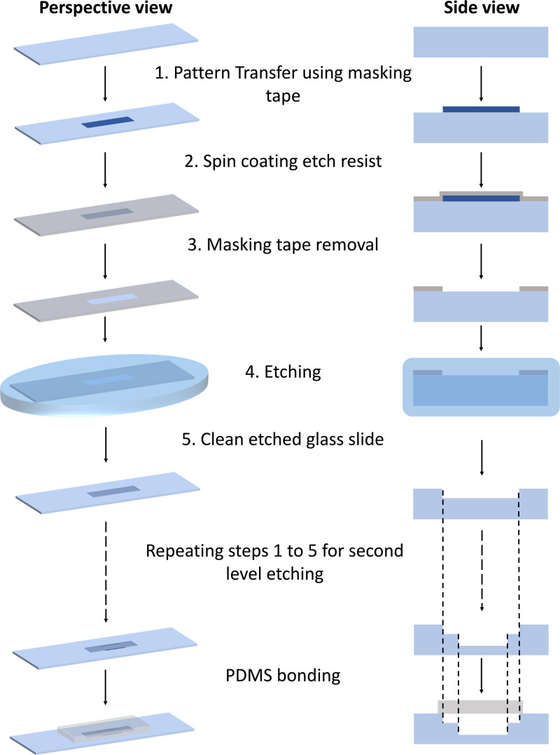
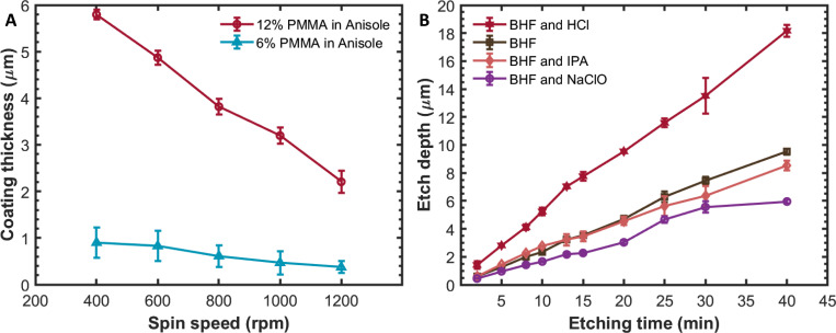
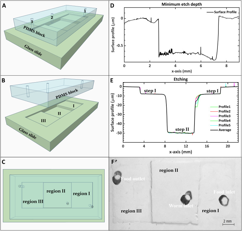
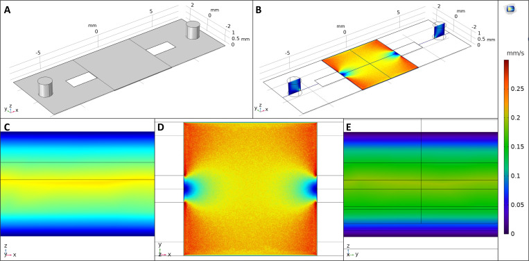
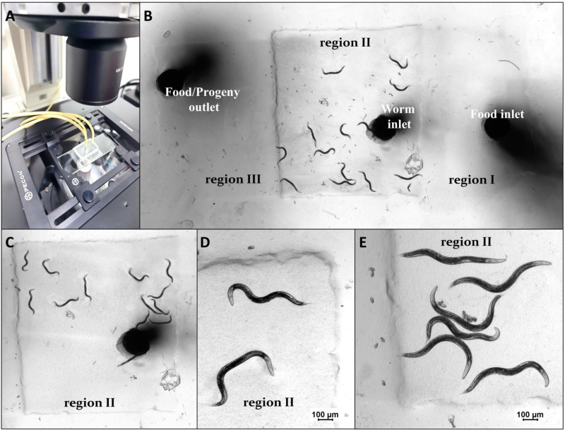
Microfluidic devices, through their vast applicability as tools for miniaturized experimental setups, have become indispensable for cutting edge research and diagnostics. However, the high operational cost and the requirement of sophisticated equipment and clean room facility for the fabrication of these devices make their use unfeasible for many research laboratories in resource limited settings. Therefore, with the aim of increasing accessibility, in this article, we report a novel, cost-effective micro-fabrication technique for fabricating multi-layer microfluidic devices using only common wet-lab facilities, thereby significantly lowering the cost. Our proposed process-flow-design eliminates the need for a mastermold, does not require any sophisticated lithography tools, and can be executed successfully outside a clean room. In this work, we also optimized the critical steps (such as spin coating and wet etching) of our fabrication process and validated the process flow and the device by trapping and imaging Caenorhabditis elegans. The fabricated devices are effective in conducting lifetime assays and flushing out larvae, which are, in general, manually picked from Petri dishes or separated using sieves. Our technique is not only cost effective but also scalable, as it can be used to fabricate devices with multiple layers of confinements ranging from 0.6 to more than 50 m, thus enabling the study of unicellular and multicellular organisms. This technique, therefore, has the potential to be adopted widely by many research laboratories for a variety of applications.
© 2023 Author(s).
Conflict of interest statement
The authors have no conflicts to disclose.
Figures
Similar articles
-
Making Healthcare Accessible: A Rapid Clean-Room-Free Fabrication Strategy for Microfluidics-Driven Biosensors Based on Coupling Stereolithography and Hot Embossing.ACS Omega. 2024 Aug 23;9(36):38096-38106. doi: 10.1021/acsomega.4c05196. eCollection 2024 Sep 10. ACS Omega. 2024. PMID: 39281898 Free PMC article.
-
Double-Sided Tape in Microfluidics: A Cost-Effective Method in Device Fabrication.Biosensors (Basel). 2024 May 15;14(5):249. doi: 10.3390/bios14050249. Biosensors (Basel). 2024. PMID: 38785723 Free PMC article. Review.
-
Biomedical microfluidic devices by using low-cost fabrication techniques: A review.J Biomech. 2016 Jul 26;49(11):2280-2292. doi: 10.1016/j.jbiomech.2015.11.031. Epub 2015 Nov 27. J Biomech. 2016. PMID: 26671220 Review.
-
Micro-Macro: Selective Integration of Microfeatures Inside Low-Cost Macromolds for PDMS Microfluidics Fabrication.Micromachines (Basel). 2019 Aug 30;10(9):576. doi: 10.3390/mi10090576. Micromachines (Basel). 2019. PMID: 31480301 Free PMC article.
-
3D-printed microfluidic devices.Biofabrication. 2016 Jun 20;8(2):022001. doi: 10.1088/1758-5090/8/2/022001. Biofabrication. 2016. PMID: 27321137 Review.
References
-
- Tippo T., Thanachayanont C., Muthitamongkol P., Junin C., Hietschold M., and Thanachayanont A., “The effects of solvents on the properties of ultra-thin poly (methyl methacrylate) films prepared by spin coating,” Thin Solid Films 546, 180–184 (2013). 10.1016/j.tsf.2013.05.022 - DOI
-
- Mehta V. and Rath S. N., “3D printed microfluidic devices: A review focused on four fundamental manufacturing approaches and implications on the field of healthcare,” Bio-Des. Manuf. 4(2), 311–343 (2021). 10.1007/s42242-020-00112-5 - DOI
LinkOut - more resources
Full Text Sources
Miscellaneous