. 2023 Jun 21;13(1):10067.
doi: 10.1038/s41598-023-36790-1.

Engineering-geological comparative analysis of four cases studies of waste landfills

Affiliations

Engineering-geological comparative analysis of four cases studies of waste landfills

Marian Marschalko et al. Sci Rep. .

Abstract

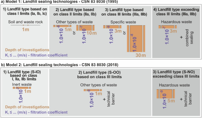
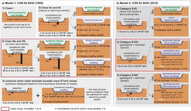
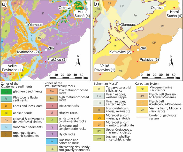
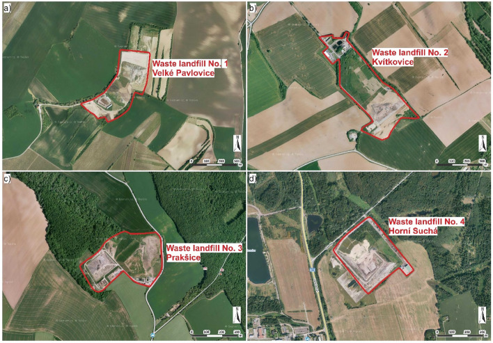
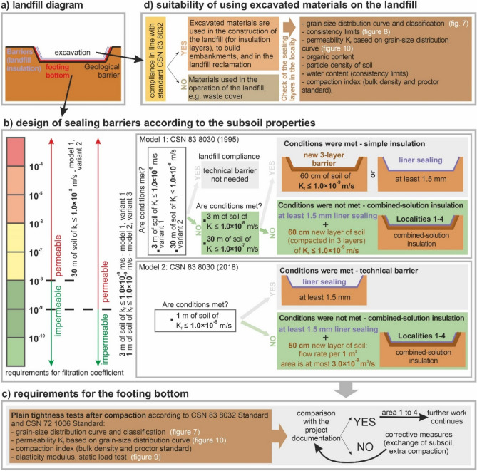
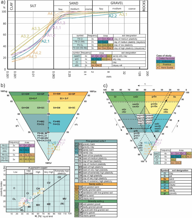
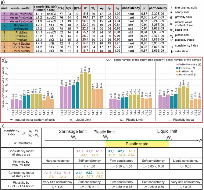
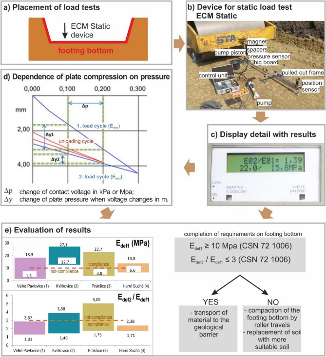
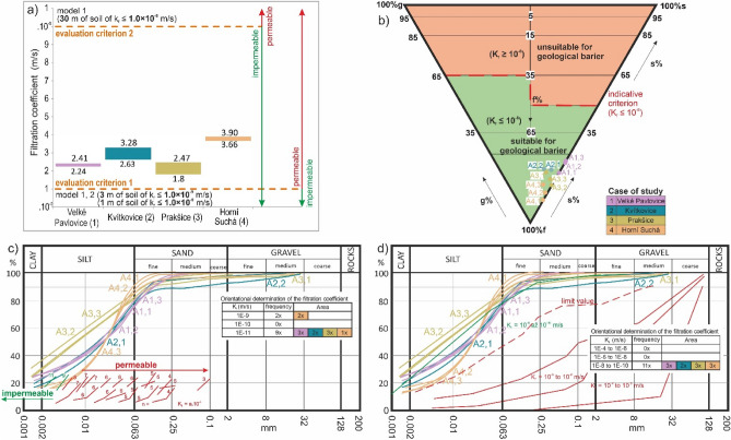
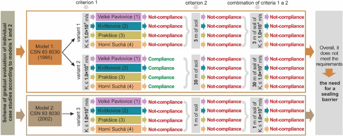
The aim of the paper is to carry out a comparative engineering-geological study of four different waste landfills using the evaluation criteria for the geological subsoil as a natural sealing barrier. The study evaluates 4 localities (Velké Pavlovice, Kvítkovice, Prakšice and Horní Suchá) using three variants (based on two standards) which approach the geological barrier requirements as a combination of impermeability requirements based on a filtration coefficient limit value. and the required geometry represented by investigation depths. The research was carried out in landfills in Moravia, in the east of the Czech Republic. The study's motivation is to point at the differences in engineering-geological investigations of waste landfills (as for the requirements for impermeable geological subsoil as a natural sealing barrier) when compared with other engineering structures (where the main goal is to evaluate load-bearing capacity and settlement). The purpose of the geological barrier is to prevent the spread of contamination, and the paper shows this can be approached differently, as shown in two different methodologies investigated herein. The first model (Model 1) assumes there is a 3-m-thick subsoil below the landfill's footing bottom, which manifests impermeability characterized by the filtration coefficient Kf ≤ 1.0 * 10-9 m/s, or a 30-m-thick subsoil of Kf ≤ 1.0 * 10-8 m/s. The second model (Model 2) assumes a 1-m thick, impermeable subsoil massif of Kf ≤ 1.0 * 10-9 m/s. We found that none of the landfills in the four selected localities had an impermeable layer in the required depth (a filtration coefficient Kf from 1.8 * 10-9 to 3.9 * 10-9 m/s), and thus did not comply with the limiting conditions. As a result, an anthropogenic technical barrier had to be installed. An important goal of the study from an environmental point of view was to assess the existence of a suitable geological barrier under the proposed landfills. The most important criterion from this point of view is permeability. An additional technical objective of the project was also the assessment of the possible creation of a technical anthropogenic isolation barrier. In the event that the natural sealing barrier would not be sufficient. This was shown in all solved case studies of engineering geological investigations of waste landfills.


Conflict of interest statement

The authors declare no competing interests.

Figures

Figure 1
Figure 1
Requirements for the landfill’s geological subsoil (two parameters—the depth of the engineering-geological investigation, and the impermeability of the geological environment based on filtration coefficient) in the sense of the geological barrier for the disposal of waste based on landfill categories and the limit leachability values (Table 1); (a) Model 1 according to CSN 83 8030 Standard, (b) Model 2 according to CSN 83 8030 Standard.
Figure 2
Figure 2
Conditions for applying technical barriers: (a) Model 1 according to CSN 83 8030, (b) Model 2 according to CSN 83 8030.
Figure 3
Figure 3
Maps of the area of interest, (a) map of engineering-geological zones, (b) map of geological division. Schematic figures made by the authors using CorelDRAW Graphic Suite 2019 software www.coreldraw.com.
Figure 4
Figure 4
Interest localities of the four waste landfills, (a) aerial photo of waste landfill 1 in Velké Pavlovice, (b) aerial photo of waste landfill 2 in Kvítkovice, (c) aerial photo of waste landfill 3 in Prakšice, and (d) aerial photo of waste landfill 4 in Horní Suchá; Aerial photographs obtained with permission from www.seznam.cz.
Figure 5
Figure 5
Requirements and research aim, (a) landfill diagram, (b) design of sealing barriers according to the subsoil properties, (c) requirements for the footing bottom, (d) suitability of using excavated materials on the landfill.
Figure 6
Figure 6
Reference classification triangles of permeability and impermeability of the geological environment related to sandy, gravel and fine-grained soils (foundation soils), (a1) classification triangle of soil permeability (based on filtration coefficient), (a2) classification triangle of soil suitability for artificial infiltration, (b1) classification triangle of impermeability, (b2) classification triangle of soil suitability for the geological barrier (example for Model 1, waste landfill categories 2 and 3).
Figure 7
Figure 7
Classification of the case studies according to the foundation soil classification, (a) grain-size distribution curve, (b) classification triangle of foundation soils based on CSN 73 1001, (c) classification triangle of foundation soils based on CSN EN ISO 14,688–2 (72 1003).
Figure 8
Figure 8
Selected soil properties in the case study localities 1, 2, 3 and 4 (a) table of soil properties, (b) charts with water content, liquid limit, plastic limit and plasticity index (c) classification of the localities in terms of consistencies.
Figure 9
Figure 9
Soil compressibility of case study localities 1, 2, 3 and 4 (a) placement of load tests, (b) device for static load test ECM Static, (c) display detail with results, (d) dependence of plate compression on pressure, (e) Evaluation of results.
Figure 10
Figure 10
(a) Filtration coefficient in four localities 1, 2, 3 and 4, (b) classification triangle of soil suitability for the geological barrier (example for Model 1, landfill categories 2 and 3), (c) indicative value of permeability based on grain-size distribution curve (d) indicative filtration coefficient based on grain-size distribution curve using permeability curves.
Figure 11
Figure 11
Diagram of assessment criteria to evaluate the tightness of the geological environment (natural geological barrier) for the purposes of establishing landfills in 4 localities (no. 1 Velké Pavlovice, no. 2 Kvítkovice, no. 3 Prakšice and no. 4 Horní Suchá) and final assessment (all 4 case studies do not meet the criteria and an anthropogenic barrier must be installed).

References

    1. Ersoy H, Bulut F, Berkün M. Landfill site requirements on the rock environment: A case study. Eng. Geol. 2013;154:20–35. doi: 10.1016/j.enggeo.2012.12.005. - DOI
    1. Huang Y, Fan G. Engineering geological analysis of municipal solid waste landfill stability. Nat. Hazards. 2016;84(1):93–107. doi: 10.1007/s11069-016-2408-8. - DOI
    1. Israde-Alcantara I, Delgado OB, Chavez AC. Geological characterization and environmental implications of the placement of the Morelia dump, Michoacán, central Mexico. J. Air Waste Manag. Assoc. 2005;55(6):755–764. doi: 10.1080/10473289.2005.10464665. - DOI - PubMed
    1. Xiang R, Xu Y, Liu YQ, Lei GY, Liu JC, Huang QF. Isolation distance between municipal solid waste landfills and drinking water wells for bacteria attenuation and safe drinking. Sci. Rep. 2019;9(1):1–11. doi: 10.1038/s41598-019-54506-2. - DOI - PMC - PubMed
    1. Bouazza, A. & Kavazanjian Jr, E. Construction on former landfills. In Proceedings 2nd ANZ Conference on Environmental Geotechnics, Newcastle (pp. 467–482) (2004).