Review
. 2023 Jun 22;9(1):15.
doi: 10.1186/s40729-023-00483-1.

Zygoma implant under function: biomechanical principles clarified

Affiliations
Review

Zygoma implant under function: biomechanical principles clarified

Edmond Bedrossian et al. Int J Implant Dent. .

Abstract

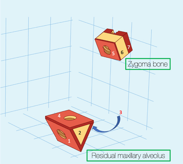
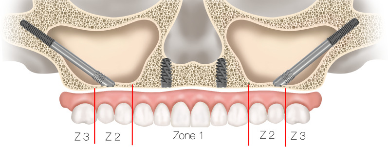
Purpose: The purpose of this document is to clarify the biomechanical principles involved when zygoma implants are placed under functional loads.

Methods: Two independent reviewers conducted electronic search of the literature from January 2000 to February 2023 describing the biomechanical principles involved using the zygoma implant for maxillary reconstruction. Articles describing the stresses within the zygoma implant, the maxillary bone and the zygoma bone under functional loads were included.

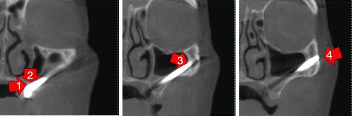
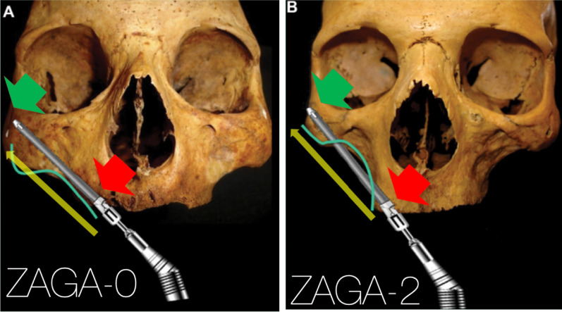
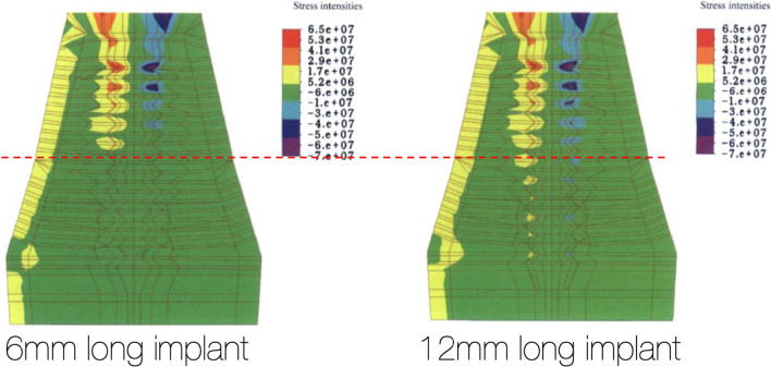
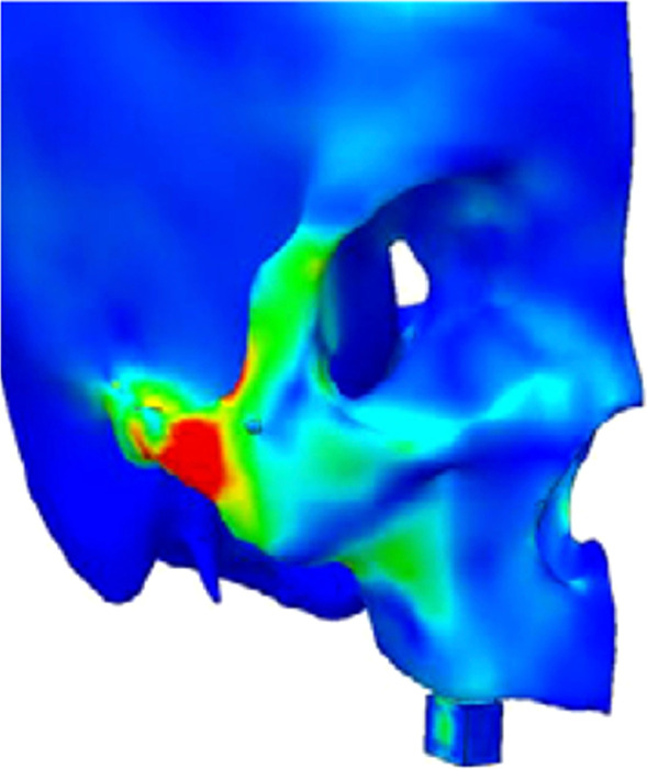
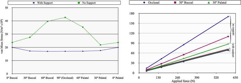
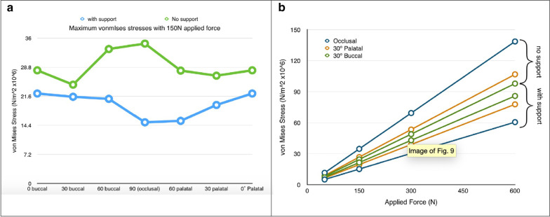
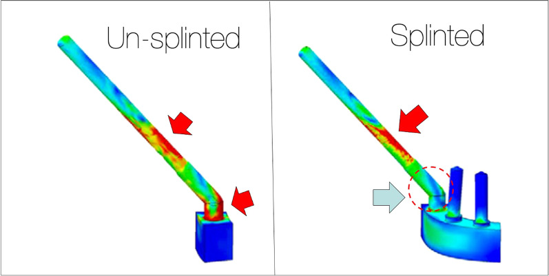
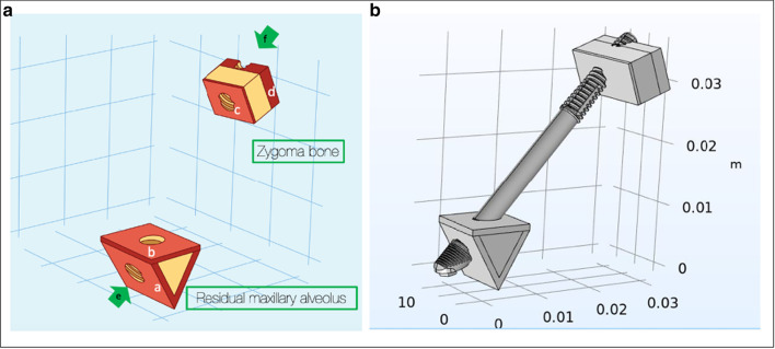
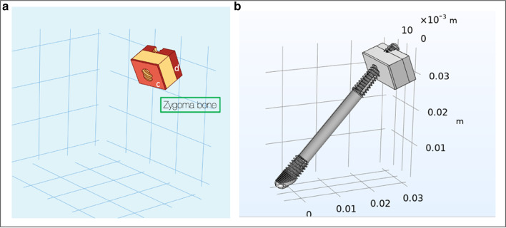
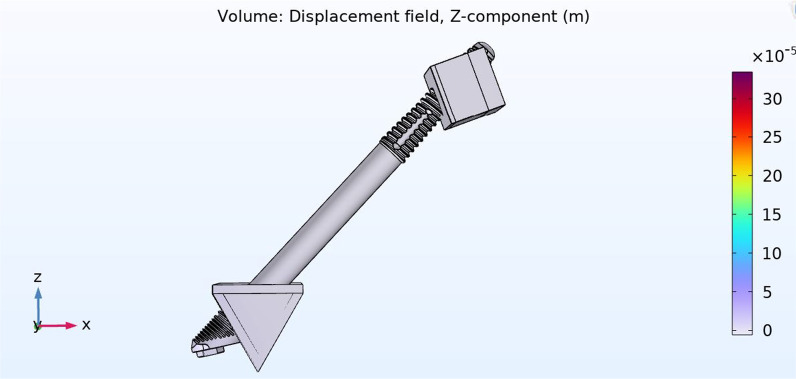
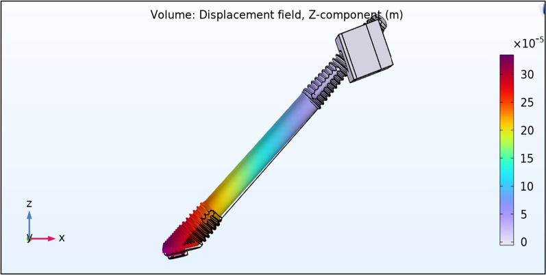
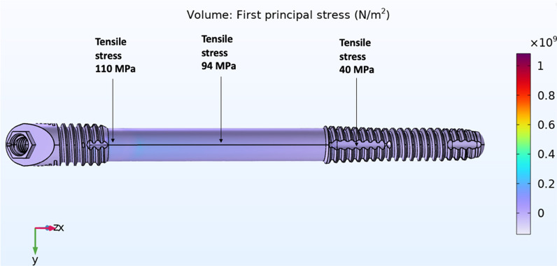
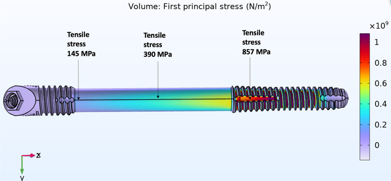
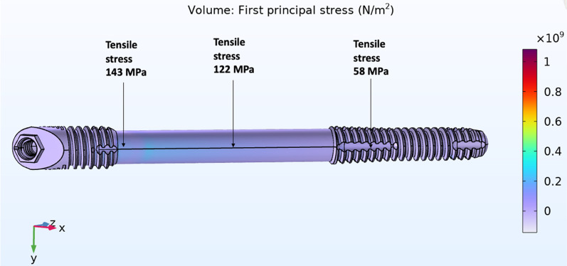
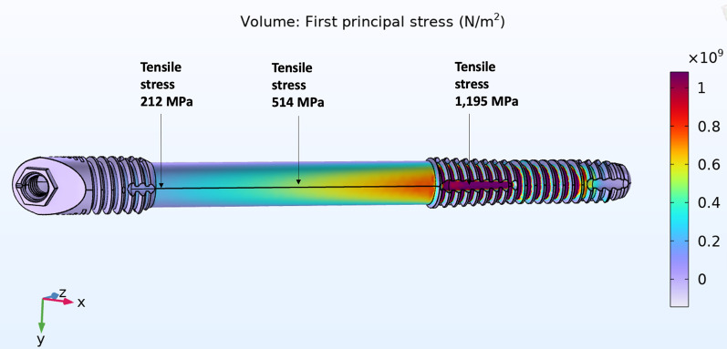
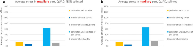
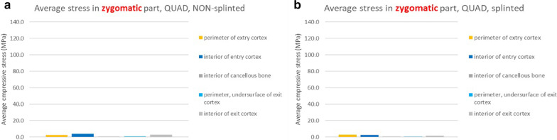
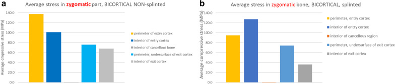
Results: The lack of maxillary boney support at the implant platform resulted in significant higher stress measured within the zygoma implant as well as the zygoma bone.

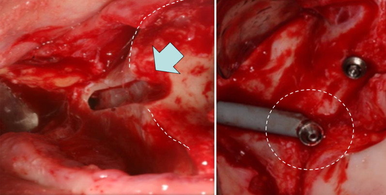
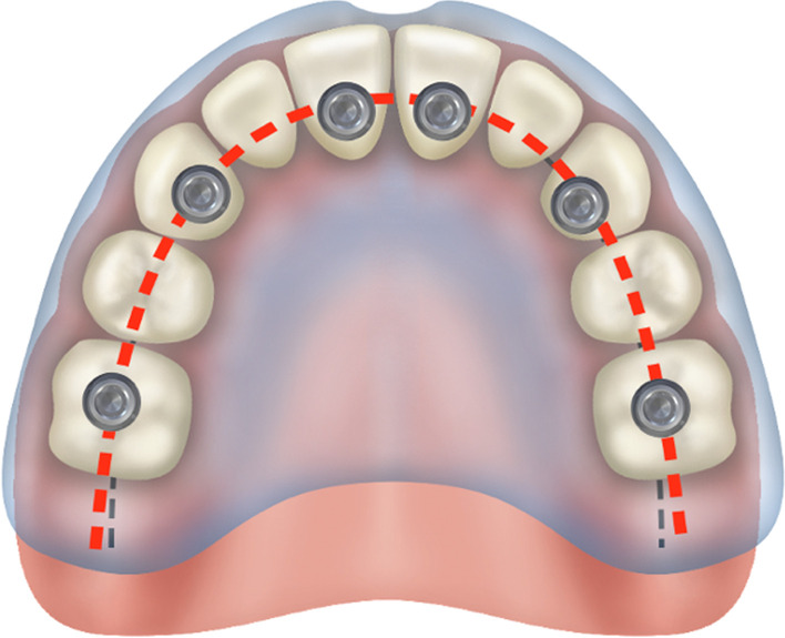
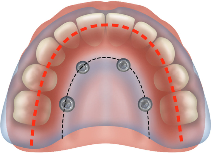
Conclusion: The maxilla is the primary support when zygoma implants are placed under functional loads. Quad-cortical stabilization of the zygoma implants and their cross-arch stabilization are recommended to reduce the degree of stress whenever possible.


Conflict of interest statement

Not applicable.

Figures

Fig. 1
Fig. 1
With the OST, the red arrows indicate the quad-cortically stabilized zygoma implant. 1. Lingual plate of maxillary alveolus; 2. floor of sinus; 3. roof of sinus; 4. lateral cortical plate of zygoma bone
Fig. 2
Fig. 2
a, b The starting point and the end point are represented by the red and green arrows, respectively. The yellow arrow represents the implant trajectory which is exactly the same in a representing the OST and b representing the “extra-sinus” technique; from Kato et al.
Fig. 3
Fig. 3
The red-dotted line shows the concentration of loads to be the same in 6-mm-long implant as well as a 12-mm-long implant
Fig. 4
Fig. 4
Point “JU” has the densest boney topography
Fig. 5
Fig. 5
The illumination of the masseter muscle on the zygomatic arch during centric occlusion as described by Ujigawa
Fig. 6
Fig. 6
Increased loads at the zygoma implant platform in absence of maxillary crestal boney support
Fig. 7
Fig. 7
The arrow points to the intentional removal of the maxillary crestal bone. The implant platform is not supported by the maxillary alveolus
Fig. 8
Fig. 8
a, b Increased loads in centric occlusion as well as in lateral excursion without maxillary alveolar support
Fig. 9
Fig. 9
Ujigawa; arrows indicate the stress within the zygoma implant. Significant reduction of occlusal loads, grey arrow, when the zygoma implant is cross-arch splinted
Fig. 10
Fig. 10
The Skalak and the Morgan and James model
Fig. 11
Fig. 11
a, b The quad-cortical (BBQ) and bicortically (BBB) stabilized surgical models
Fig. 12
Fig. 12
ad Cross-arch splinted BBQ and BBB models (a, b) and the lone-standing BBQ and BBB models (c, d)
Fig. 13
Fig. 13
1, is the cortical lingual wall of the residual maxillary alveolus. 2, the cancellous portion of the residual maxillary alveolus. 3, the cortical buccal wall of the residual maxillary alveolus. 4, the cortical floor of the maxillary sinus. 5, the cortical wall of the base of the zygoma bone (roof of the maxillary sinus).6, the cancellous bone of the body of the zygoma bone. 7, the cortical outer cortex of the zygoma bone
Fig. 14
Fig. 14
a, b Trajectory and the quad-cortical points for stabilizing the zygoma implant
Fig. 15
Fig. 15
a, b Bi-cortical points for the zygoma implant stabilized only with in the zygoma bone
Fig. 16
Fig. 16
11 µm of vertical displacement on the quad-cortically stabilized zygoma implant
Fig. 17
Fig. 17
300 µm of vertical displacement on the bicortically stabilized zygoma implant
Fig. 18
Fig. 18
Cross-arch splinted zygoma implants with the premaxillary implants
Fig. 19
Fig. 19
Quad-cortical, cross-arch splinted z-implant – stresses in the implant combined horizontal + vertical loading
Fig. 20
Fig. 20
BICORTICAL, cross-arch splinted z-implant – stresses in the implant. Combined horizontal + vertical loading
Fig. 21
Fig. 21
Lone standing zygoma implant
Fig. 22
Fig. 22
QUAD, free-standing z-implant – stresses in the implant. Combined horizontal + vertical loading
Fig. 23
Fig. 23
Bi-cortical, free-standing z-implant – stresses in the implant. Combined horizontal + vertical loading
Fig. 24
Fig. 24
Points for the measurement of the stresses within maxilla and the zygoma bone
Fig. 25
Fig. 25
a, b BBQ non-splinted and splinted model showing the stress within the maxillary alveolar bone under functional loading
Fig. 26
Fig. 26
a, b BBQ non-splinted and splinted model showing the stress within the zygoma bone under functional loading
Fig. 27
Fig. 27
a, b BBB non-splinted and splinted model showing the stress within the maxillary alveolar bone under functional loading
Fig. 28
Fig. 28
Zones of the maxilla determine the indication for the zygoma concept
Fig. 29
Fig. 29
Zones of the maxilla determines the indication for the quad-zygoma concept
Fig. 30
Fig. 30
ZAGA classification, describes the contour of the lateral sinus wall and the position of the residual maxillary crest
Fig. 31
Fig. 31
The zygomatic anatomic classification
Fig. 32
Fig. 32
Superimposition of the of ZAGA 0 to ZAGA 4, the various levels of sinus wall concavity is illustrated by different colors
Fig. 33
Fig. 33
Non-resorbed maxilla with the arch form, red-dotted line. Superimposed on the arch form, the black-dotted line
Fig. 34
Fig. 34
Placement of the zygoma implant platform on the resorbed residual ridge with the prosthetic access holes palatal to red-dotted line

References

    1. Brånemark PI, Gröndahl K, Ohrnell LO, Nilsson P, Peterson B, Svensson B, Engstrand P, Nannmark U. Zygoma fixture in the management of advanced atrophy of the maxilla: technique and long-term results. Scand J Plast Reconstr Surg Hand Surg. 2004;38(2):70–85. doi: 10.1080/02844310310023918. - DOI - PubMed
    1. Bedrossian E, Rangers B, Stumpel L, Indersano T. Immediate function with the zygomatic implant: a graftless solution for the patient with mild to advanced atrophy of the maxilla. Int J Oral Maxillofac Implants. 2006;21:937–942. - PubMed
    1. Chow J, Hui E, Lee PK, et al. Zygomatic implants—protocol for immediate occlusal loading: a preliminary report. J Oral Maxillofac Surg. 2006;64:804–811. doi: 10.1016/j.joms.2006.01.021. - DOI - PubMed
    1. Branemark PI. Surgery and fixture installation: zygomaticus fixture clinical procedures. Gothenburg, Sweden, Nobel Biocare AB; 1998, pp. 1.
    1. Petruson B. Sinuscopy in patients with titanium implants in the nose and sinus. Scand J Plast Reconstr Surg Hand Surg. 2004;38:86–93. doi: 10.1080/02844310310023909. - DOI - PubMed

Substances

LinkOut - more resources