Review
. 2023 Jun 7;13(6):630.
doi: 10.3390/bios13060630.

Flexible and Wearable Biosensors for Monitoring Health Conditions

Affiliations
Review

Flexible and Wearable Biosensors for Monitoring Health Conditions

Zhimin Song et al. Biosensors (Basel). .

Abstract

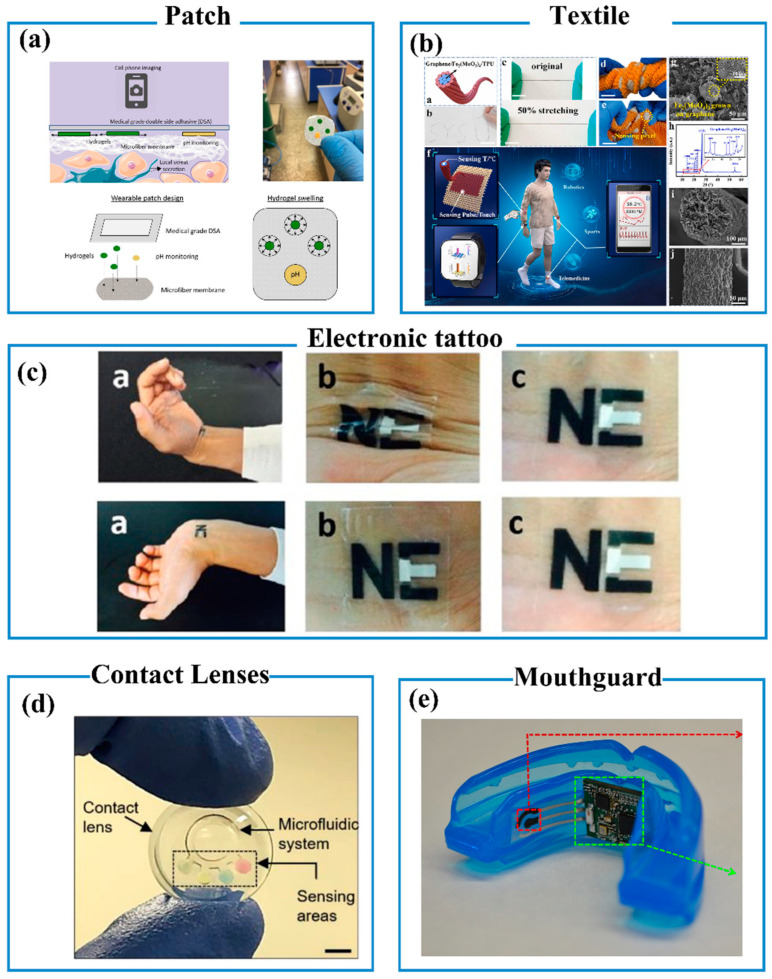
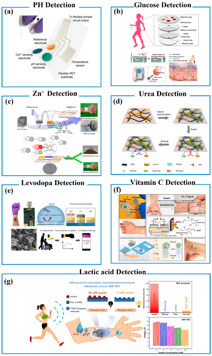
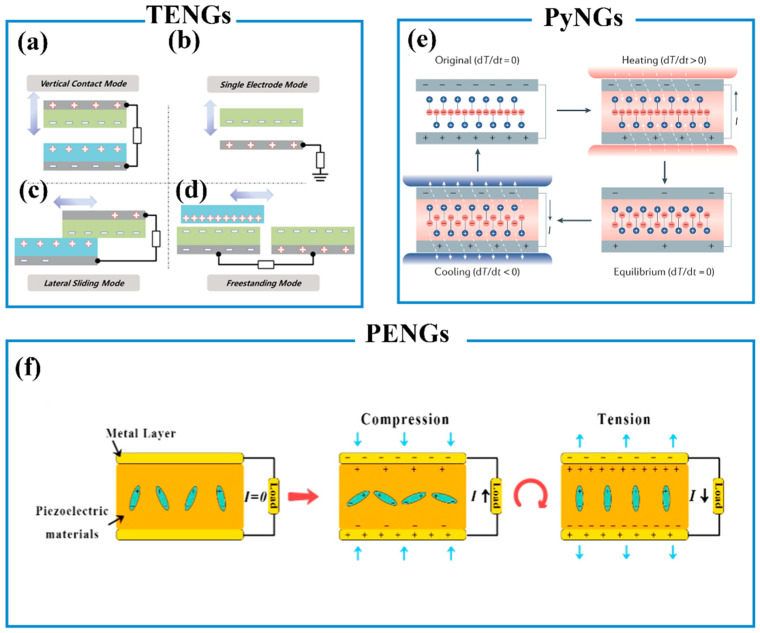
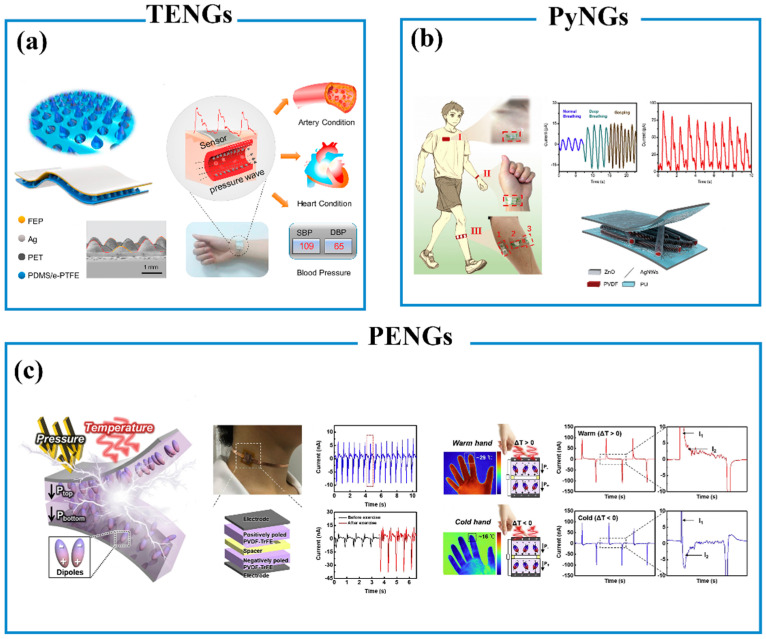
Flexible and wearable biosensors have received tremendous attention over the past decade owing to their great potential applications in the field of health and medicine. Wearable biosensors serve as an ideal platform for real-time and continuous health monitoring, which exhibit unique properties such as self-powered, lightweight, low cost, high flexibility, detection convenience, and great conformability. This review introduces the recent research progress in wearable biosensors. First of all, the biological fluids often detected by wearable biosensors are proposed. Then, the existing micro-nanofabrication technologies and basic characteristics of wearable biosensors are summarized. Then, their application manners and information processing are also highlighted in the paper. Massive cutting-edge research examples are introduced such as wearable physiological pressure sensors, wearable sweat sensors, and wearable self-powered biosensors. As a significant content, the detection mechanism of these sensors was detailed with examples to help readers understand this area. Finally, the current challenges and future perspectives are proposed to push this research area forward and expand practical applications in the future.

Keywords: E-skins; self-powered biosensors; sweat sensors; wearable sensors.


Conflict of interest statement

The authors declare no conflict of interest.

Figures

Figure 3
Figure 3
Application manners of wearable sensors. (a) Patch [101]. Copyright 2020, Elsevier B.V. (b) Textile. Copyright 2022, Elsevier Ltd. [105]. (c) Electronic tattoo [109]. Copyright 2014, Elsevier B.V. (d) Contact lenses [116]. Copyright 2020, Elsevier B.V. (e) Mouthguard [121]. Copyright 2015, Elsevier B.V.
Figure 6
Figure 6
(a) A schematic diagram of a flexible sensor array consisting of Ca2+, pH, and temperature sensors patterned on a flexible PET substrate. Reproduced with permission [166]. Copyright 2016, American Chemical Society. (b) Schematic illustration of the sensor composed of four layers, including the five detection chambers containing the pre-embedded colorimetric reagents in the top layer. Reproduced with permission [170]. Copyright 2019, American Chemical Society. (c) Schematic description of the fabrication process of the wearable sensing device. Reproduced with permission [173]. Copyright 2019, American Chemical Society. (d) A schematic diagram of a flexible sensor to detect urea. Reproduced with permission [174]. Copyright 2018, American Chemical Society. (e) Schematic of the sweatband and levodopa sensing mechanism. Reproduced with permission [175]. Copyright 2019, American Chemical Society. (f) VC determination using wearable sensors in stimulated sweat. Reproduced with permission [177]. Copyright 2020, American Chemical Society. (g) Self-powered molecularly imprinted polymers-based triboelectric sensor (MIP-TES) for non-invasive lactate monitoring in human sweat. Reproduced with permission [179]. Copyright 2022, Elsevier Ltd.
Figure 7
Figure 7
The four fundamental modes of TENGs: (a) Vertical contact mode, (b) Lateral sliding mode, (c) Single electrode mode, (d) Free-standing triboelectric layer mode. Reproduced with permission [197]. Copyright 2018, WILEY-VCH Verlag GmbH & Co. KGaA, Weinheim. (e) Working mechanism of PyNGs. Reproduced with permission [2]. Copyright 2020, Springer Nature Limited. (f) Working mechanisms of PENGs. Reproduced with permission [188]. Copyright 2020, Elsevier Ltd.
Figure 8
Figure 8
(a) Schematic diagram of a TENG-based biosensor. Reproduced with permission [202]. Copyright 2020, Elsevier Ltd. (b) Schematic diagram of a PENG-based biosensor. Reproduced with permission [195]. Copyright 2020, Elsevier Ltd. (c) Schematic diagram of TENG/PyNG-based biosensor. Reproduced with permission [203]. Copyright 2020, Elsevier Ltd.
Figure 1
Figure 1
Schematic illustration of typical surface processing. (a) PDMS molds. Reproduced with permission from [75]. Copyright 2020, The Authors. (b) Natural plants. Reproduced with permission from [76]. Copyright 2014, WILEY-VCH Verlag GmbH & Co. KGaA, Weinheim. (c) Salt and instant sugar as templates. Reproduced with permission from [77]. Copyright 2019, American Chemical Society.
Figure 2
Figure 2
(a) Fabrication process flow of the active bimodal sensor array by laser cutting. Reproduced with permission [83]. Copyright 2020, Wiley-VCH GmbH. (b) Fabrication process of stretchable and conformable matrix network by photolithography. Reproduced with permission [86]. Copyright 2018, The Author(s). (c) Schematic diagram of the ink-jet printing process for the patterned PPSR sensor. Reproduced with permission. Copyright 2014, WILEY-VCH Verlag GmbH & Co. KGaA, Weinheim [89]. (d) Schematic representation of vapor deposition employed to fabricate pressure sensor arrays. Reproduced with permission [90]. Copyright 2017, The Author(s).
Figure 4
Figure 4
(a) Schematic illustration of the fabrication of a flexible sensor. Images showing (b) the bendability of the sensor, (c) the morphology of Au NWs-coated tissue fibers (scale bar = 100 μm). (d) Schematic illustration of the sensing mechanism. (e) Current changes in responses to loading and unloading. Reproduced with permission [140]. Copyright, 2014, Nature Publishing Group, a division of Macmillan Publishers Limited.
Figure 5
Figure 5
(a) Schematic of the fabrication process of BNF@PDMS. (b) Photograph (top) and schematic (bottom) of BN/PDMS-based capacitive sensor. Plots of ΔC/C0 as a function of applied (c) noncontact touch by hovering a finger (red) and a tweezer (blue) at close proximity to the device, and (d) environmental change by gently blowing through the device. The insets in (b) show the photographs of a hovering finger (boxed in red) and tweezer (boxed in blue) on top of the device [70]. Copyright, 2020 WILEY-VCH Verlag GmbH & Co. KGaA, Weinheim.

Similar articles

Cited by

References

    1. Yang Y., Gao W. Wearable and Flexible Electronics for Continuous Molecular Monitoring. Chem. Soc. Rev. 2019;48:1465–1491. doi: 10.1039/C7CS00730B. - DOI - PubMed
    1. Zheng Q., Tang Q., Wang Z.L., Li Z. Self-Powered Cardiovascular Electronic Devices and Systems. Nat. Rev. Cardiol. 2021;18:7–21. doi: 10.1038/s41569-020-0426-4. - DOI - PubMed
    1. Gao Y., Yu L., Yeo J.C., Lim C.T. Flexible Hybrid Sensors for Health Monitoring: Materials and Mechanisms to Render Wearability. Adv. Mater. 2020;32:1902133. doi: 10.1002/adma.201902133. - DOI - PubMed
    1. Yang J.C., Mun J., Kwon S.Y., Park S., Bao Z., Park S. Electronic Skin: Recent Progress and Future Prospects for Skin-Attachable Devices for Health Monitoring, Robotics, and Prosthetics. Adv. Mater. 2019;31:1904765. doi: 10.1002/adma.201904765. - DOI - PubMed
    1. Chen X., Luo F., Yuan M., Xie D., Shen L., Zheng K., Wang Z., Li X., Tao L. A Dual-Functional Graphene-Based Self-Alarm Health-Monitoring E-Skin. Adv. Funct. Mater. 2019;29:1904706. doi: 10.1002/adfm.201904706. - DOI