Review
. 2023 Jun 17;15(12):2716.
doi: 10.3390/polym15122716.

A Review of Critical Issues in High-Speed Vat Photopolymerization

Affiliations
Review

A Review of Critical Issues in High-Speed Vat Photopolymerization

Sandeep Kumar Paral et al. Polymers (Basel). .

Abstract

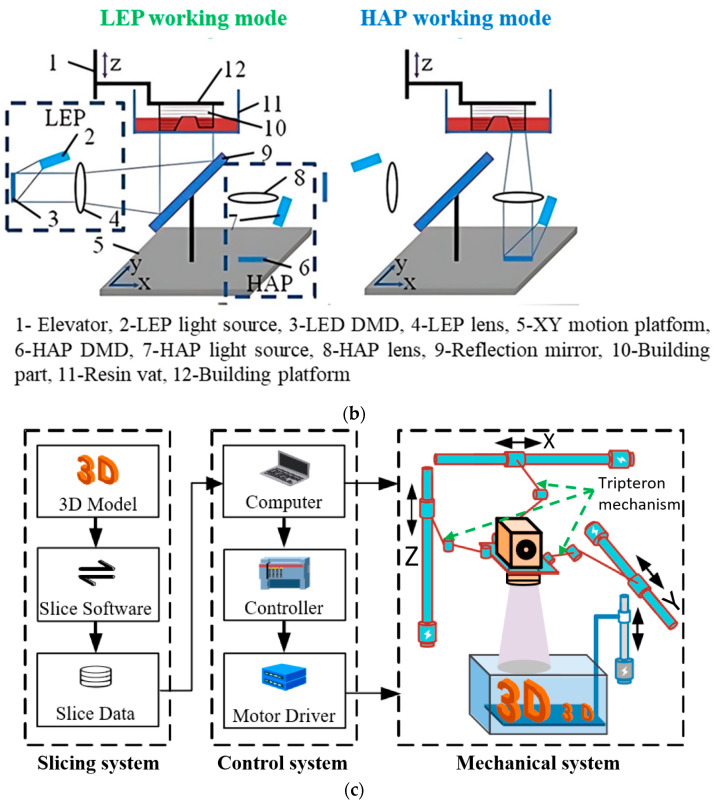
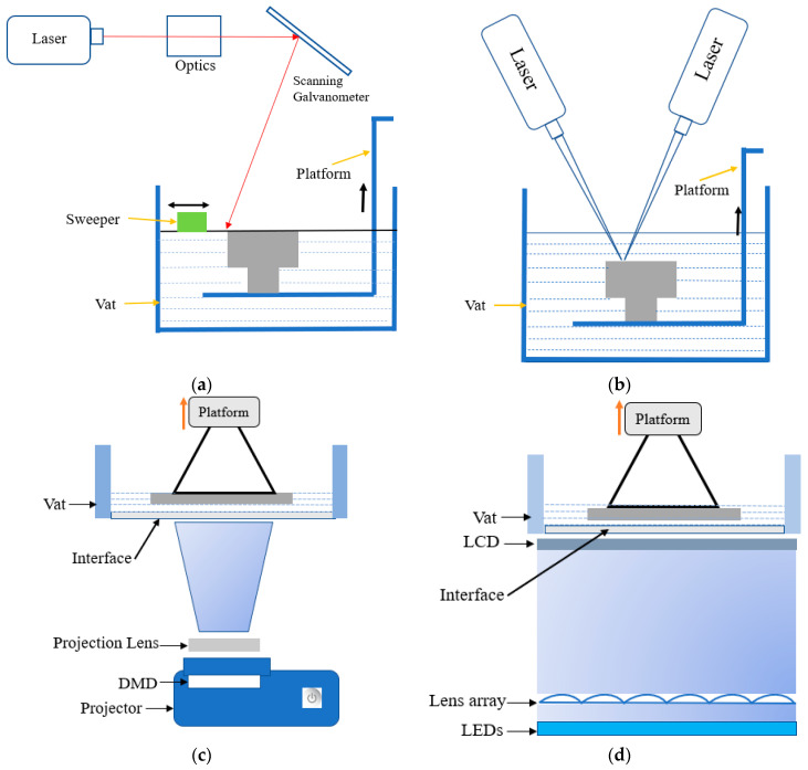
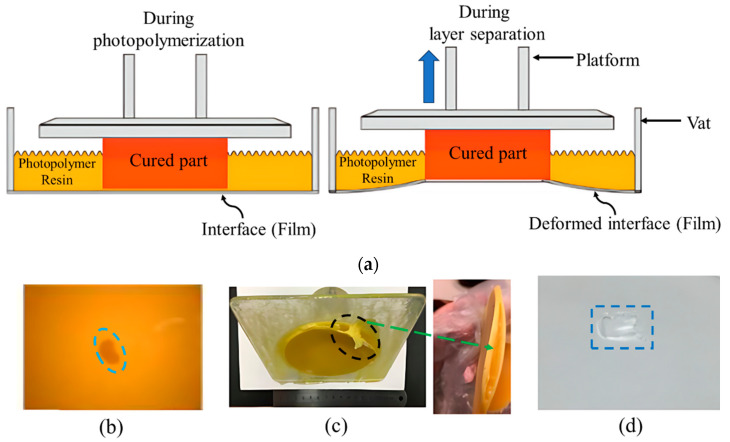
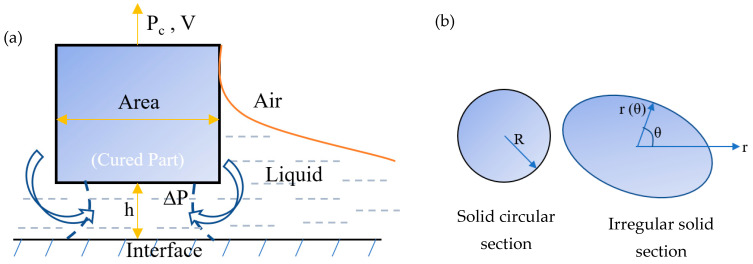
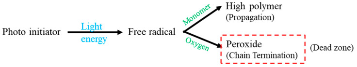
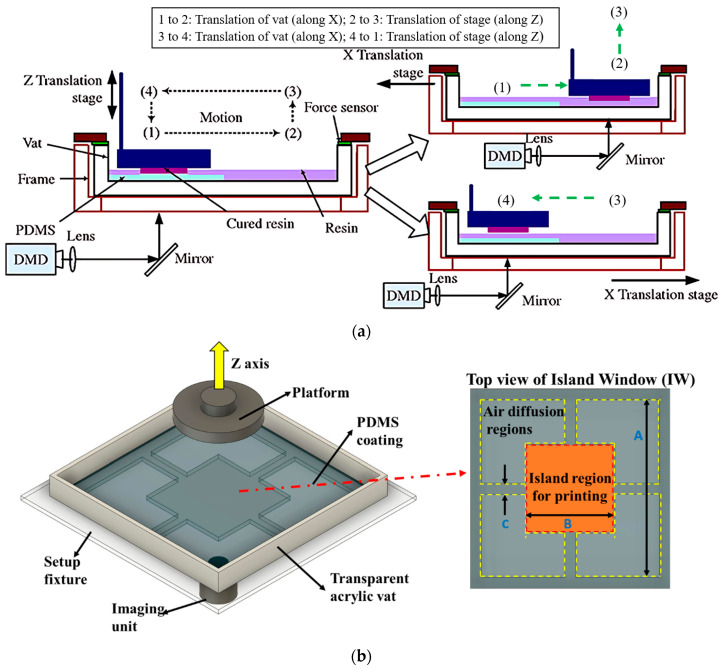
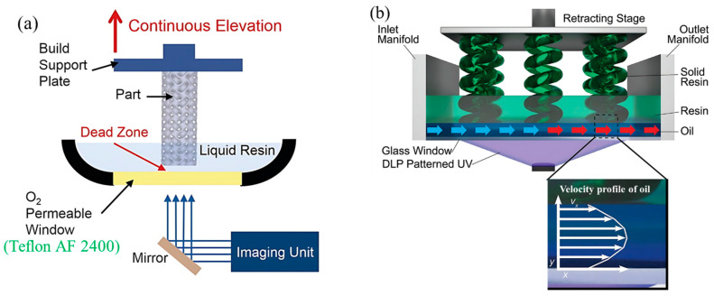
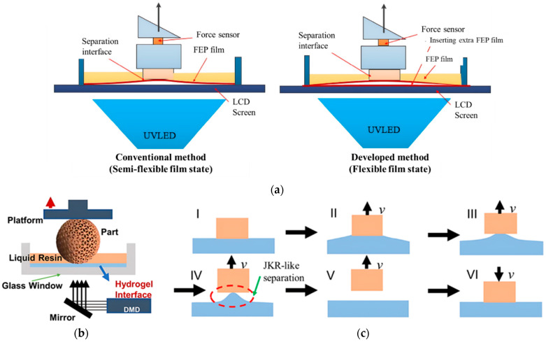
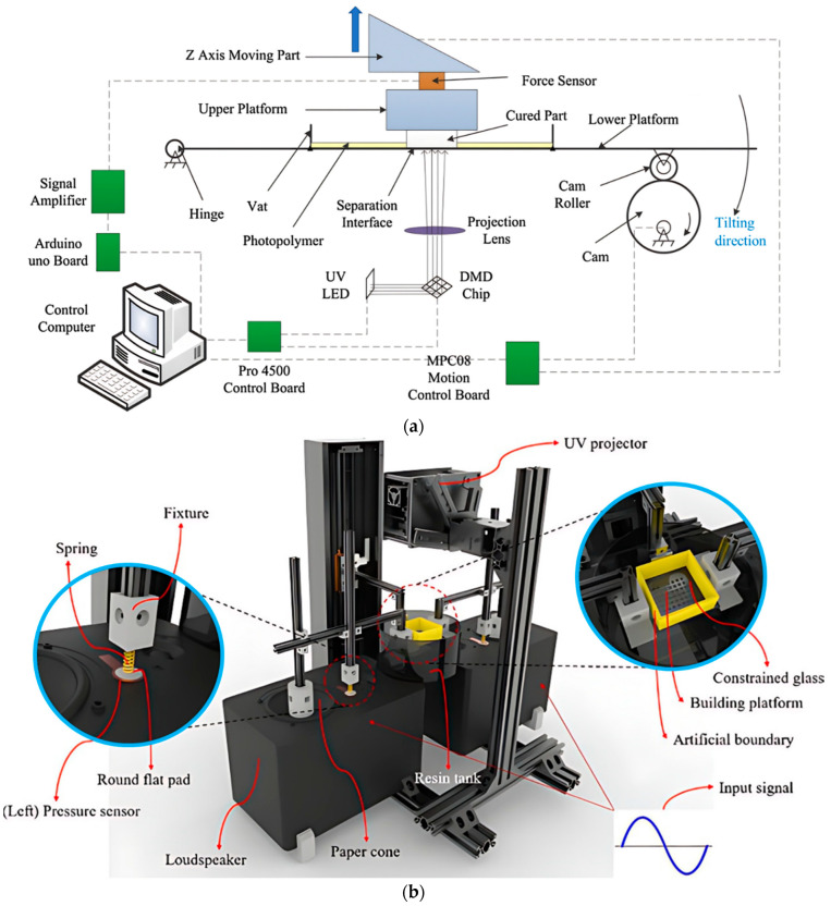
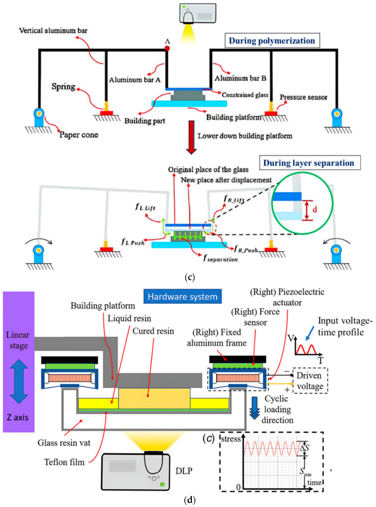
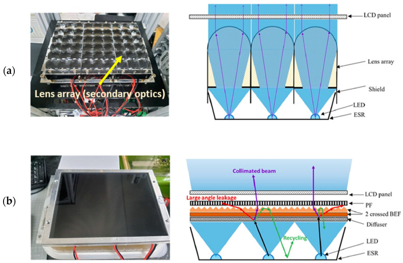
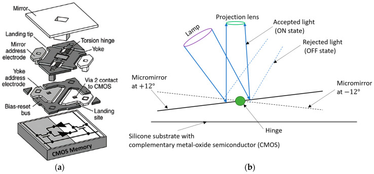
Vat photopolymerization (VPP) is an effective additive manufacturing (AM) process known for its high dimensional accuracy and excellent surface finish. It employs vector scanning and mask projection techniques to cure photopolymer resin at a specific wavelength. Among the mask projection methods, digital light processing (DLP) and liquid crystal display (LCD) VPP have gained significant popularity in various industries. To upgrade DLP and LCC VPP into a high-speed process, increasing both the printing speed and projection area in terms of the volumetric print rate is crucial. However, challenges arise, such as the high separation force between the cured part and the interface and a longer resin refilling time. Additionally, the divergence of the light-emitting diode (LED) makes controlling the irradiance homogeneity of large-sized LCD panels difficult, while low transmission rates of near ultraviolet (NUV) impact the processing time of LCD VPP. Furthermore, limitations in light intensity and fixed pixel ratios of digital micromirror devices (DMDs) constrain the increase in the projection area of DLP VPP. This paper identifies these critical issues and provides detailed reviews of available solutions, aiming to guide future research towards developing a more productive and cost-effective high-speed VPP in terms of the high volumetric print rate.

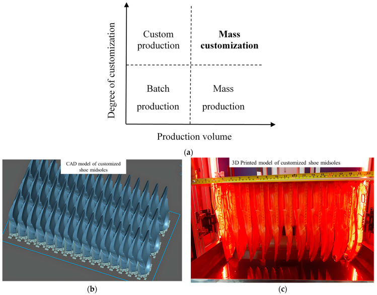
Keywords: digital light processing (DLP); high-speed VPP; liquid crystal display (LCD); mass customization; resin refilling; separation force.


Conflict of interest statement

The authors declare that they have no known competing financial interests or personal relationships that could have appeared to influence the work reported in this paper.

Figures

Figure 5
Figure 5
Separation mechanisms for solid–solid interaction. (a) Crack propagation based on CZM. (b) The traction separation relation of bilinear CZM’s constitutive parameters. (c) Detachment of a flat rigid punch from an elastic film. Schematic diagram showing two typical separation modes (DMT like and JKR like) based on 𝜂 [39,55].
Figure 5
Figure 5
Separation mechanisms for solid–solid interaction. (a) Crack propagation based on CZM. (b) The traction separation relation of bilinear CZM’s constitutive parameters. (c) Detachment of a flat rigid punch from an elastic film. Schematic diagram showing two typical separation modes (DMT like and JKR like) based on 𝜂 [39,55].
Figure 14
Figure 14
(a) Schematic representation of the standard RGB LCD. Reproduced from [84]. (b) Diagram of the unpolarized light of LED array passes through components in LCD VPP. Reproduced with permission from [90]. (c) Schematic arrangement of the LED’s primary and secondary optics in standard LCD VPP.
Figure 19
Figure 19
Printing area increment methods of DLP VPP. (a) Schematic machine setup of the scanning projection stereolithography (SPSL). Reproduced with permission from [130]. (b) Schematic representation of double mask projection stereolithography (DMPSL). Reproduced with permission from [133]. (c) Increment of the projection area by tripteron parallel mechanism. Reproduced from [136].
Figure 19
Figure 19
Printing area increment methods of DLP VPP. (a) Schematic machine setup of the scanning projection stereolithography (SPSL). Reproduced with permission from [130]. (b) Schematic representation of double mask projection stereolithography (DMPSL). Reproduced with permission from [133]. (c) Increment of the projection area by tripteron parallel mechanism. Reproduced from [136].
Figure 1
Figure 1
The publications and citations statistics made for VPP from the year 2016 to 12 June 2023. (source: Web of Science).
Figure 2
Figure 2
Schematic diagrams of VPP processes. (a) Laser-based SLA VPP. (b) TPP VPP. (c) DLP VPP. (d) LCD VPP. Reproduced from [13,20].
Figure 3
Figure 3
(a) Classification of production methods. (b,c) Mass customization by using LCD VPP to arrange near similar geometries on the same platform. (b) CAD models of shoe midsoles. (c) Printed models of shoe midsoles.
Figure 4
Figure 4
(a) Schematic diagram of interface deformation due to the platform’s upward movement in the bottom-up VPP. (bd) Printing failure and defects due to the high separation force. (b) Holes on the printed surface, (c) separate printed layers, and (d) broken film (interface), which acts as a constrained surface. (bd) Reproduced from [38].
Figure 6
Figure 6
Separation mechanism for solid–liquid interaction. (a) The uncured resin presents in between the cured part and the interface to create the dead zone of thickness h. (b) Schematic view of the solid circular section and irregular solid section of the printed geometry [38].
Figure 7
Figure 7
Dead zone formation in free radical polymerization.
Figure 8
Figure 8
Interface modification by using PDMS in different ways. (a) Schematic demonstration of two-stage resin vat process. Reproduced with permission from [44]. (b) Schematic representation of the island window (IW) design of the vat. Reproduced from [59].
Figure 9
Figure 9
Interface modification by maintaining constant dead zone thickness. (a) Schematic view of continuous liquid interface production (CLIP) by supplying pure oxygen beneath the oxygen-permeable window. Reproduced with permission from [63]. (b) Schematic representation of the high area rapid printing (HARP) process by using the laminar flow of fluorinated oil at the top of the glass window. Reproduced with permission from [66].
Figure 10
Figure 10
(a) Schematic diagram of the flexible and semi-flexible film state using FEP films. Reproduced with permission from [67]. (b) Schematic representation of DLP VPP setup by using the ultra-soft hydrogel as an interface material. (c) Schematic process of JKR-like separation on a soft hydrogel interface. Reproduced with permission from [51].
Figure 11
Figure 11
Process modifications for separation force reduction. (a) Schematic representation of the vat tilting motion by using a cam, roller, and hinge joint. Reproduced with permission from [69]. (b) Machine setup and (c) schematic view of the working mechanism of the vibration-assisted system using a loudspeaker of 60 Hz. Reproduced with permission from [70]. (d) Schematic illustration of the vibration-assisted DLP VPP machine setup using piezoelectric actuators. Reproduced with permission from [71].
Figure 11
Figure 11
Process modifications for separation force reduction. (a) Schematic representation of the vat tilting motion by using a cam, roller, and hinge joint. Reproduced with permission from [69]. (b) Machine setup and (c) schematic view of the working mechanism of the vibration-assisted system using a loudspeaker of 60 Hz. Reproduced with permission from [70]. (d) Schematic illustration of the vibration-assisted DLP VPP machine setup using piezoelectric actuators. Reproduced with permission from [71].
Figure 12
Figure 12
Photopolymer resin refilling for newly cured layer beneath the previous cured part. (a) Schematic representation of the bioprinting interface. Schematic view of the continuous replenishment of the hydrogel below the curing part. (b) Tracked trajectories path of fluorescence microbeads during the vacuum refilling created by previous layer printing. Reproduced with permission from [79].
Figure 13
Figure 13
(a) Microscopic images of different sizes of laser-fabricated microchannels in the PDMS interface. Reproduced with permission from [80]. (b) Schematic and SEM view of the nanotextured PDMS interface. Reproduced with permission from [81].
Figure 15
Figure 15
Schematic view of LED package structures (primary optics). (a) High-power nanostructure LED packaging inspired by firefly light organ. Reproduced with permission from [99]. (b) TiO2-doped silicon layer with silicone lens LED packaging. Reproduced with permission from [100]. (c) Quantum dot (QD)-based LED with crater silicon lens. Reproduced from [101].
Figure 16
Figure 16
Collimating lens design of LED secondary optics. (a) Two-dimensional form of collimating lens consisting of three freeform surfaces, spherical and ellipsoidal surfaces. Reproduced with permission from [116]. (b) Two-dimensional form of collimating lens consisting of two aspherical surfaces. Reproduced with permission from [117].
Figure 17
Figure 17
LED modules for LCD VPP. (a) The commercial lens array LED module. (b) A developed LED module by using the diffuser, BEF, and PF. Reproduced from [123].
Figure 18
Figure 18
Schematic diagram of digital micromirror device (DMD). (a) The exploded view of a single DMD pixel consisting of a micromirror. Reproduced from [124]. (b) The working mechanism of the individual micromirror.

References

    1. Jungst T., Smolan W., Schacht K., Scheibel T., Groll J. Strategies and Molecular Design Criteria for 3D Printable Hydrogels. Chem. Rev. 2015;116:1496–1539. doi: 10.1021/acs.chemrev.5b00303. - DOI - PubMed
    1. Wendel B., Rietzel D., Kühnlein F., Feulner R., Hülder G., Schmachtenberg E. Additive Processing of Polymers. Macromol. Mater. Eng. 2008;293:799–809. doi: 10.1002/mame.200800121. - DOI
    1. Zheng X., Lee H., Weisgraber T.H., Shusteff M., DeOtte J., Duoss E.B., Kuntz J.D., Biener M.M., Ge Q., Jackson J.A., et al. Ultralight, ultrastiff mechanical metamaterials. Science. 2014;344:1373–1377. doi: 10.1126/science.1252291. - DOI - PubMed
    1. Chen D., Zheng X. Multi-material Additive Manufacturing of Metamaterials with Giant, Tailorable Negative Poisson’s Ratios. Sci. Rep. 2018;8:9139. doi: 10.1038/s41598-018-26980-7. - DOI - PMC - PubMed
    1. Melchels F.P.W., Feijen J., Grijpma D.W. A review on stereolithography and its applications in biomedical engineering. Biomaterials. 2010;31:6121–6130. doi: 10.1016/j.biomaterials.2010.04.050. - DOI - PubMed

LinkOut - more resources