[Preprint]. 2025 Jan 25:2023.05.30.542747.
doi: 10.1101/2023.05.30.542747.

Spatial periodicity in grid cell firing is explained by a neural sequence code of 2-D trajectories

Affiliations

Spatial periodicity in grid cell firing is explained by a neural sequence code of 2-D trajectories

R G Rebecca et al. bioRxiv. .

Update in

Abstract

Spatial periodicity in grid cell firing has been interpreted as a neural metric for space providing animals with a coordinate system in navigating physical and mental spaces. However, the specific computational problem being solved by grid cells has remained elusive. Here, we provide mathematical proof that spatial periodicity in grid cell firing is the only possible solution to a neural sequence code of 2-D trajectories and that the hexagonal firing pattern of grid cells is the most parsimonious solution to such a sequence code. We thereby provide a likely teleological cause for the existence of grid cells and reveal the underlying nature of the global geometric organization in grid maps as a direct consequence of a simple local sequence code. A sequence code by grid cells provides intuitive explanations for many previously puzzling experimental observations and may transform our thinking about grid cells.

Keywords: cell sequences; grid cells; path integration; trajectory coding.


Conflict of interest statement

Conflicts of Interest: The authors declare no competing interests.

Figures
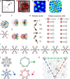
Figure 1.
Figure 1.. Spatially periodic firing of grid cells in 2-D space emerges from a neural sequence code of trajectories.
A, Schematic drawing of a 1 × 1 m2 environment surrounded by walls in the presence of a single visual cue card. B, Trajectory plot visualizing grid cell spiking activity as a function of the animal’s location in space. Data obtained from the medial entorhinal cortex of a freely foraging mouse,. The black line indicates the path taken by the animal. Red dots indicate the locations where action potentials (spikes) were generated by the grid cell. C, Firing rate map of the spiking data shown in A. Data are visualized as 3 × 3 cm2 spatial bins, smoothed with a Gaussian kernel. Red and blue colors indicate high and low firing rates. Peak and average firing rates are 15 and 1.9 Hz. D, Spatial autocorrelogram of the data shown in B. Red and blue colors indicate high and low correlation values. E, The animal’s current position and velocity determine the animal’s trajectory. In a sequence code, directions are represented by pairs of sequentially active cell assemblies with non-overlapping cellular composition. We refer to the individual members in a set of completely distinct cell assemblies as elements. The red circle represents the currently active element. The next active element in the sequence code is uniquely determined by the currently active cell and the velocity vector (Definition 8). N = North, NE = Northeast, NW = Northwest, W = West, SW = Southwest, and SE = Southeast. F, Elements’ firing fields that surround each other symmetrically in a hexagonal lattice packing allow for equal angular resolution in the coding of trajectories by cell sequences. Colors represent distinct elements. G, If an elements’ firing field was surrounded by fewer or more than six firing fields that touched each other, opposite directions would not be represented at the same angular resolution. In this example, eastwest cannot be distinguished from eastnorthwest and eastsouthwest because the three directions are represented by the same sequence of elements, yellowred. However, the opposite direction, westeast, is represented by three different cell sequences allowing for a finer angular resolution in the representation of traveling direction. H, Example of possible pairs of elements creating a sequence code. If the sequence code shall represent all directions with equal angular resolution, the cellular composition of sequentially active cell assemblies needs to be completely distinct every 60 degrees (E and F). Possible representations of velocity vectors by sequences of two elements are shown for when the currently active element is #1 or #2. Numbers within circles identify distinct elements. I, Example of a complete sequence code that uniquely represents all directions at 60 degrees resolution as a function of the currently active element and the traveling direction. J, Sequential activation of seven distinct elements can code for infinitively long trajectories along all three major axes of a hexagonal lattice. K, The same sequential activation map as in I and J but plotted in 2-D space. Note that the firing fields of individual elements form grid maps in 2-D space, as highlighted in grey for element #1.
Figure 2.
Figure 2.. Repeating sequences of elements coding for trajectories result in lattice packing of firing fields.
Left panels show firing fields of multiple distinct elements with non-overlapping firing fields arranged in a 2-D lattice packing (grid). Each grid provides a sequence code of trajectories. Mid panels show the sequences that code for the directions along the three major axes of the grid. Right panels highlight the firing fields of an individual element visualizing the type of lattice formed by the firing fields of one element. A, An example of the minimal number of seven elements and resulting sequences with repeat length 7 along the three grid axes. The resulting firing fields of individual elements (referred to as a “grid map” in animal experiments) are arranged on a hexagonal lattice rotated by 10.9 degrees against a vertical axis. B, An example of eight cells and sequences with repeat lengths 4 along one axis, and repeat length 8 along the two other axes. The resulting firing fields are arranged on a centered rectangular lattice. C, An example of nine cells and sequences with repeat length 3 along all three grid axes, resulting in hexagonal lattice packing of indivual elements’ firing fields.
Figure 3.
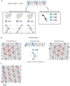
Figure 3.. The minimum number of distinct elements providing a sequence code of trajectories in 2-D space is 7, and there are exactly 2 possible arrangements of elements up to relabeling.
A, Repeat lengths that are smaller than 7 result in a violation of a sequence code of trajectories because the code would be ambiguous and not unique. A red question mark indicates that no element can be found for this position that would not violate the sequence code. Red numbers indicate that activity of this element at the current position would violate sequence coding of trajectories due to ambiquity. Blue background color marks the sequential activity of 2 elements that violate the sequence code of trajectories (Definition 8) because the next active cell in the sequence is not uniquely determined by the currently active cell and the velocity vector associated with the current trajectory of an animal. B, If the repeat length is 7, there are three potential translations of the sequence in row 1 to fill up row 2 (see Mathematical proof). Only two of those three tranlsations result in an arrangement of elements (up to relabeling of elements) that creates a sequence code for trajectories in 2-D space. These two arrangements are mirror images of each other and imply that the firing fields of each individual grid element fall on the vertices of equilateral triangles, i.e., they form a hexagonal grid. C, Both possible arrangements of firing fields imply that grid patterns of other grid elements have the same spacing and rotation, and only differ in spatial phase (compare grid patterns of element #1 and element #6). The smallest angle between one grid axis and the boundary of a rectangular enclosure is 10.9 degrees if one row of sequences is aligned with one of the borders of the enclosure.
Figure 4.
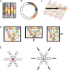
Figure 4.. Transformation of a sequence code of trajectories from 2-D space to 1-D space.
A,B, A sequence of 7 different elements can code for a trajectory in a 1-D compartmentalized “hairpin” maze (A) or a 1-D circular track (B). Note that the distance between firing fields would increase in the 1-D “hairpin” maze and 1-D circular track compared to the distance between spatial firing fields in a 2-D environment. Also note that sequences could undergo a phase reset at behaviorally relevant points, e.g., the turning points in the “hairpin” maze (A). C, The sequence of active elements in a 1-D environment can be interpreted as a cross-section of the trajectory sequence code in a 2-D space. D, Anchoring of firing filelds to environmental borders predicts parametric rescaling of an individual element’s grid pattern when a familiar enclosure is deformed. Each color represents one grid element, each circle represents one firing field. For clarity, the complete set of firing fields of an individual element is shown only for one element (orange color). In addition, sequences are shown for all three major axes. Left panel, original maze configuration. Mid and right panel, the environment is compressed along the vertical or horizontal dimension resulting in a parametric deformation of firing fields and the grid pattern of individual elements’ firing fields along the vertical or horizontal dimension. E, Progressively faster advancement from the currently active element to the next active element in the sequence code of trajectories results in progressive decrease in grid spacing and thereby a local distortion of the grid map. Open circles represent firing fields of grid elements along the three major axes. The red filled circle in the center represents a salient location such as a rewarded goal location toward which nearby grid fields gravitate.
Figure 5.
Figure 5.. Multiple grids provide nearly continuous resolution in the coding of trajectories.
A, The circles with numbers show the centers of the grid fields from 4 grids, each composed of 7 distinct elements (total of 28 grid elements). Shaded areas represent the firing fields of individual elements. Elements with non-overlapping firing fields form “grids”, shown in black, green, blue, and red colors. Each number within a circle identifies a distinct element. If elements represent cell assemblies, a combination of numbers (e.g., “1,2”) identifies a element whose cellular composition is an overlap between two elements with adjacent firing fields. E.g., element “1,2” is composed of cells that are part of elements “1” and “2”, resulting in an overlap of firing fields. For visual clarity, not all element numbers are shown. B, Grids #2, #3, and #4 are phase-shifted along one of the three major axes of grid #1. The emerging grid map of an individual element’s firing fields is highlighted in color for one grid element in each grid. The phase-shift of each grid is indicated by showing the transparent grid pattern of grid #1. C, When more grid elements are added, the elements can be represented in 3-D neural space as a neural manifold, shown here for a total of 1792 grid elements forming 256 grids of non-overlapping firing fields. The colored cells represent one diagonal axis across rows of non-repeating elements if plotted in the 2-D plane as shown in A.

References

    1. Fyhn M., Molden S., Witter M. P., Moser E. I. & Moser M.-B. Spatial representation in the entorhinal cortex. Science 305, 1258–1264 (2004). - PubMed
    1. Hafting T., Fyhn M., Molden S., Moser M.-B. & Moser E. I. Microstructure of a spatial map in the entorhinal cortex. Nature 436, 801–806 (2005). - PubMed
    1. Boccara C. N. et al. Grid cells in pre- and parasubiculum. Nat. Neurosci. 13, 987–994 (2010). - PubMed
    1. Fuhs M. C. & Touretzky D. S. A spin glass model of path integration in rat medial entorhinal cortex. J. Neurosci. Off. J. Soc. Neurosci. 26, 4266–4276 (2006). - PMC - PubMed
    1. McNaughton B. L., Battaglia F. P., Jensen O., Moser E. I. & Moser M.-B. Path integration and the neural basis of the ‘cognitive map’. Nat Rev Neurosci 7, 663–678 (2006). - PubMed

Publication types