Review
. 2023 Jul 4;25(7):euad191.
doi: 10.1093/europace/euad191.

Practical guidance to reduce radiation exposure in electrophysiology applying ultra low-dose protocols: a European Heart Rhythm Association review

Affiliations
Review

Practical guidance to reduce radiation exposure in electrophysiology applying ultra low-dose protocols: a European Heart Rhythm Association review

Philipp Sommer et al. Europace. .

Abstract

Interventional electrophysiology offers a great variety of treatment options to patients suffering from symptomatic cardiac arrhythmia. Catheter ablation of supraventricular and ventricular tachycardia has globally evolved a cornerstone in modern arrhythmia management. Complex interventional electrophysiological procedures engaging multiple ablation tools have been developed over the past decades. Fluoroscopy enabled interventional electrophysiologist throughout the years to gain profound knowledge on intracardiac anatomy and catheter movement inside the cardiac cavities and hence develop specific ablation approaches. However, the application of X-ray technologies imposes serious health risks to patients and operators. To reduce the use of fluoroscopy during interventional electrophysiological procedures to the possibly lowest degree and to establish an optimal protection of patients and operators in cases of fluoroscopy is the main goal of modern radiation management. The present manuscript gives an overview of possible strategies of fluoroscopy reduction and specific radiation protection strategies.

Keywords: Radiation awareness; Radiation dosage reduction; Radiation protection; Ultra low-dose protocols.


Conflict of interest statement

Conflict of interest: P.S. is a member of the Advisory Board of Abbott, Biosense Webster, Boston Scientific, and Medtronic. V.S. has no conflicts of interest to declare. M.A. is a consultant for Biosense Webster and Boston Scientific, clinical proctor for Medtronic, and has received educational grants from Abbott. R.T. is a consultant for Biosense Webster, Abbott, and Boston Scientific, and a speaker for Medtronic. H.L. has no conflicts of interest to declare. A.B. is a consultant for Biotronik, Abbott, and Biosense Webster, clinical proctor for Biotronik and Abbott, and has received educational grants from Boston Scientific.

Figures

Graphical Abstract
Graphical Abstract
3D, 3-dimensional; EP, electrophysiology; μSv, μSievert.
Figure 1
Figure 1
Schematic setup of X-ray systems. The patient entrance dose is relevant for deterministic radiation injuries and is measured in Gy (air kerma). The dose area product is measured between the tube and the patient’s body, and the unit is Gy*cm2.
Figure 2
Figure 2
Calculator for different units used for the dose area product. Typically, µGy*m2 or Gy*cm2 are used. The multiple manufacturers use different units. © www.bfs.de (Bundesamt für Strahlenschutz).
Figure 3
Figure 3
Safety measures and techniques used to decrease X-ray radiation during electrophysiology procedures.
Figure 4
Figure 4
Left operator protected with protective visors. Right operator protected with protective gloves (dark grey), protective goggles, and a brain cap.
Figure 5
Figure 5
Lead shield below the table including an overlapping shield flap (grey). Scattered radiation can further be reduced using a simple lead mattress.
Figure 6
Figure 6
Suspended radiation protection system ‘Zero-gravity’.
Figure 7
Figure 7
Gonad protection (female right, male left).
Figure 8
Figure 8
Combination of a 3D map (CARTO) with a fluoroscopic image. 3D map of the left ventricle in left anterior oblique (left image) and right anterior oblique projection (right image).
Figure 9
Figure 9
Fluoroscopic acquisitions of electrophysiology catheters (cryoballoon and circular mapping catheter) placed inside a thoracic phantom model. The detector entrance doses of the fluoroscopy system (Artis zee, Siemens AG, Forchheim, Germany) were systematically increased from 6 nGy per pulse to 66 nGy per pulse at a constant X-ray tube voltage of 112 kV. Increasing the dose results in improvement of overall image quality, however relevant details (markers and electrodes) can still be identified at the lowest dose level (6 nGy).
Figure 10
Figure 10
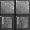
Corresponding clinical fluoroscopic images displayed in standard (A, C) and ULD (B, D) settings.
Figure 11
Figure 11
Crucial phases of ICE-guided transseptal puncture. (A) The guide wire is directed to the superior vena cava. (B) The transseptal sheath is advanced by the visual control over the wire, and its position is ascertained by the saline injection which forms ‘bubbles’ on the ICE image. (C) Then the needle is loaded and the whole instrument is pulled back while maintaining rotation towards the septum. (D) Gentle rotations clockwise and counterclockwise allow for proper positioning of the transseptal sheath towards the septum, showing typical tenting sign (arrow). (E) The needle is advanced (upper arrow), and penetration to the left atrium may be clearly visualized by the saline injection forming ‘bubbles’ on ICE image (lower arrow). (F) Once the dilator is placed together with the needle in the left atrium, the sheath is advanced while keeping the dilator in a stable position with the needle retracted. IAS, interatrial septum; LA, left atrium; LSPV, left superior pulmonary vein; SVC, superior vena cava; TSN, transseptal needle; TS, tenting on the septum; TSS, transseptal sheath.
Figure 12
Figure 12
Comparison between annual background radiation and different interventions. PCI, percutaneous coronary intervention; FRA-JFK, Frankfurt to John F. Kennedy (adapted from Schreiber et al.).

Similar articles

Cited by

References

    1. Walters TE, Kistler PM, Morton JB, Sparks PB, Halloran K, Kalman JM. Impact of collimation on radiation exposure during interventional electrophysiology. Europace 2012;14:1670–3. - PubMed
    1. Suzuki S, Furui S, Yamakawa T, Isshiki T, Watanabe A, Iino Ret al. . Radiation exposure to patients’ skin during cardiac resynchronization therapy. Europace 2009;11:1683–8.. - PubMed
    1. Rehani MM, Vano E, Ciraj-Bielac O, Kleiman NJ. Radiation and cataract. Radiat Prot Dosimetry 2011;147:300–4. - PubMed
    1. Stewart FA, Akleyev AV, Hauer-Jensen M, Hendry JH, Kleiman NJ, Macvittie TJet al. . ICRP statement on tissue reactions and early and late effects of radiation in normal tissues and organs—threshold doses for tissue reactions in a radiation protection context. Ann ICRP 2012;41:1–322. - PubMed
    1. Mathews JD, Forsythe AV, Brady Z, Butler MW, Goergen SK, Byrnes GBet al. . Cancer risk in 680 000 people exposed to computed tomography scans in childhood or adolescence: data linkage study of 11 million Australians. BMJ 2013;346:f2360. - PMC - PubMed