. 2023 Apr 27:14:e00425.
doi: 10.1016/j.ohx.2023.e00425. eCollection 2023 Jun.

Pressure-controlled microfluidics for automated single-molecule sample preparation

Affiliations

Pressure-controlled microfluidics for automated single-molecule sample preparation

Anxiong Yang et al. HardwareX. .

Abstract

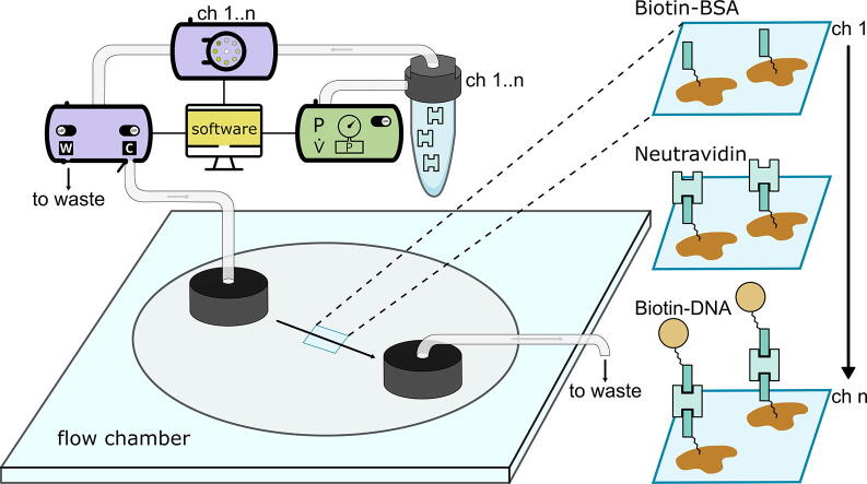
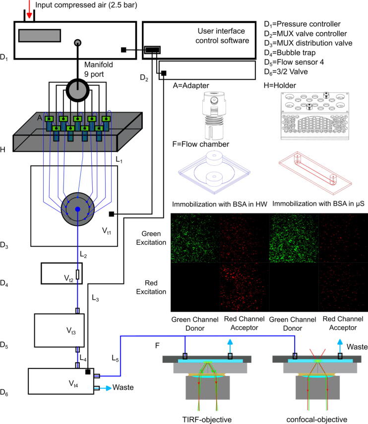
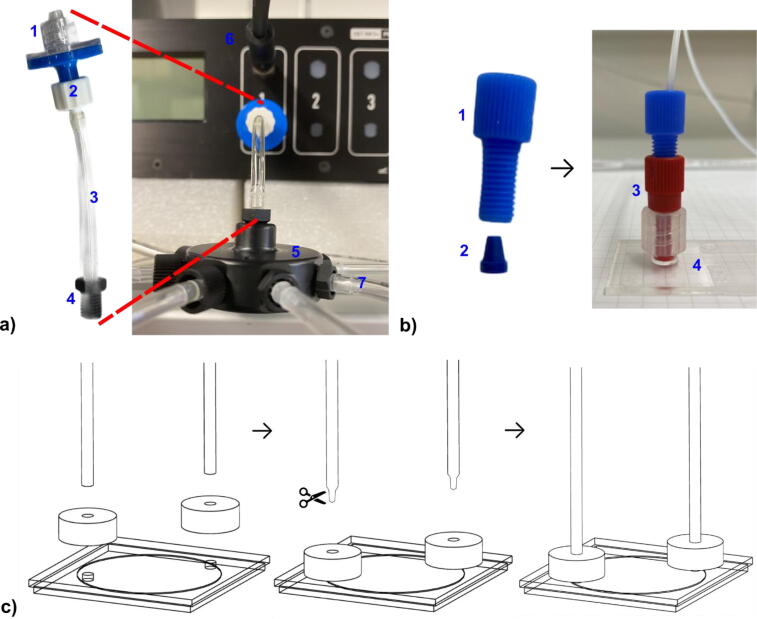
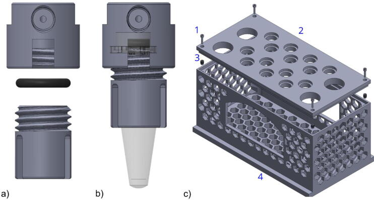
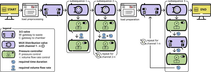
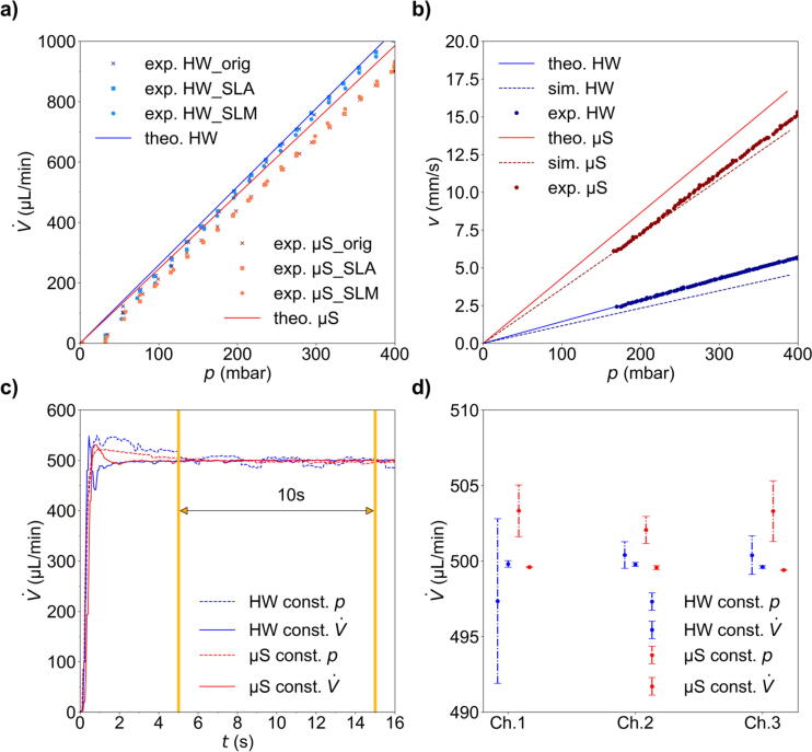
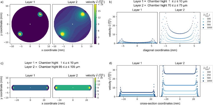
Sample preparation is a crucial step in single-molecule experiments and involves passivating the microfluidic sample chamber, immobilizing the molecules, and setting experimental buffer conditions. The efficiency of the experiment depends on the quality and speed of sample preparation, which is often performed manually and relies on the experience of the experimenter. This can result in inefficient use of single-molecule samples and time, especially for high-throughput applications. To address this, a pressure-controlled microfluidic system is proposed to automate single-molecule sample preparation. The hardware is based on microfluidic components from ElveFlow and is designed to be cost-effective and adaptable to various microscopy applications. The system includes a reservoir pressure adapter and a reservoir holder designed for additive manufacturing. Two flow chamber designs Ibidi µ-slide and Grace Bio-Labs HybriWell chamber are characterized, and the flow characteristics of the liquid at different volume flow rates V˙ are simulated using CFD-simulations and compared to experimental and theoretical values. The goal of this work is to establish a straightforward and robust system for single-molecule sample preparation that can increase the efficiency of experiments and reduce the bottleneck of manual sample preparation, particularly for high-throughput applications.

Keywords: Laboratory automation; Pressure-controlled Microfluidics; Single-Molecule Fluorescence Imaging; Single-Molecule Spectroscopy.


Conflict of interest statement

The authors declare that they have no known competing financial interests or personal relationships that could have appeared to influence the work reported in this paper.

Figures

None
Graphical abstract
Fig. 1
Fig. 1
Schematic representation of the pressure-controlled microfluidic system. D1-6. Commercially available components of the microfluidic system (compare Table 2), A and H. Additive-manufactured components, F. Commercially available flow chambers, Grace Bio-Labs HybriWell (blue) and Ibidi µ-slide (red). Below, the false color objective TIRF image of immobilized Cy3 (green) and Cy5 (red) labelled DNA oligonucleotides after the applied BSA passivation procedure in HybriWell (HW) and in Ibidi µ-slide (µS) are shown upon 50 ms ALEX excitation for illustration. L15. Length of tubes. Vt14 is the internal (“dead”) volume of the different components including upstream tubes (Table 3). The holder H can be combined with a buffer heater and sample heater to allow constant temperatures in the sample flow chamber.
Fig. 2
Fig. 2
a) 1. Hydrophobic filter, 2. Male luer integral lock ring to bard, 3. 3/32“ internal diameter tube, 4. Swivel barbed adapter, 5. Nine port manifold, 6. Cable connection with flow sensor, 7. Pressure outlet to reservoir No. n; b) Ibidi µ-slide flow chamber with tube connection: 1. Flangeless fitting, 2. Ferrules, 3. Male luer lock adapter, 4. Ibidi µ-slide chamber; c) Grace Bio-Labs HybriWell flow chamber tubing connection. To easily connect the tubes to the press fit tubing connectors on the adhesive HybriWell chamber one needs to cut the tubes at an angle of approximately 45°. Otherwise, the press fit tubing connectors tend to eject the tubes over time.
Fig. 3
Fig. 3
a) Exploded view of the reservoir adapters (A) upper and lower part with an O-ring in between. b) Adapter fitted with 1.5 mL Eppendorf tube. c) Holder (H) design: 1. M3 screw; 2. holder’s cover with holes for sample (small) and waste (large) reservoirs; 3. M3 thread inserts; 4. holder’s body to ensure a stable setting.
Fig. 4
Fig. 4
Flow chart of the hardware control sequence within the software ESI. The pre-processing sequence, i.e., the initialization of the microfluidic system, including subsequences 1 and 2 to fill the whole tubing system and to remove any air bubbles, is followed by the preparation sequence, i.e., the actual flow chamber preparation for single-molecule experiments, including subsequence 3. Find subsequences 1-3 in the SI Fig. 9.
Fig. 5
Fig. 5
a) Experimentally determined and theoretical volume flow rates as a function of the applied pressure for different reservoir adapters A: commercially available adapter for comparison (ElveFlow, org) and 3D printed adapters for both SLA and SLM used in combination with both chambers, Ibidi µ-slide (µS) in red and Grace Bio-Labs HybriWell (HW) in blue. b) Comparison of the simulated, theoretically calculated and experimentally determined flow velocities as a function of the applied pressure for both chambers. c) Experimentally determined volume flow rates in the exemplarily chosen channel No. 2 for both chambers as a function of time with a constant pressure set by the pressure controller (dashed) and a constant volume flow rate set to 500 µL/min (solid) controlled by the flow sensor. d) Mean value and standard deviation of the volume flow rate in c) for channels No. 1 to 3 at a given volume flow rate V˙ = 500 µL and a constant pressure (manually set by the pressure controller). The measurements were taken three times for each channel starting at 5 s to 15 s (orange interval in c).
Fig. 6
Fig. 6
Flow velocities for the Grace Bio-Labs HybriWell (a, b) and Ibidi µ-slide (c, d) flow chamber layouts exemplified for different heights z of the horizontal cross section. (a, c) 2d-velocity distribution close to the surface (Layer 1) and at half height of the chamber (Layer 2). (b, d) Flow velocities for sectional view between inlet and outlet openings for different volume flow rates V˙=100,250,500,1000μl/min.

References

    1. Wunderlich B., Nettels D., Benke S., Clark J., Weidner S., Hofmann H., Pfeil S.H., Schuler B. Microfluidic mixer designed for performing single-molecule kinetics with confocal detection on timescales from milliseconds to minutes. Nat. Protoc. 2013;8:1459–1474. doi: 10.1038/nprot.2013.082. - DOI - PubMed
    1. Fontana M., Fijen C., Lemay S.G., Mathwig K., Hohlbein J. High-throughput, non-equilibrium studies of single biomolecules using glass-made nanofluidic devices. Lab Chip. 2018;19:79–86. doi: 10.1039/c8lc01175c. - DOI - PubMed
    1. Lakowicz J.R. thirdrd ed. Springer Science+Business Media; New York: 2010. Principles of fluorescence spectroscopy. corr. at fourthth print.
    1. Hohlbein J., Gryte K., Heilemann M., Kapanidis A.N. Surfing on a new wave of single-molecule fluorescence methods. Phys. Biol. 2010;7:31001. doi: 10.1088/1478-3975/7/3/031001. - DOI - PubMed
    1. Hannes Michaelsen, Richard Börner, Optimization of an optical setup for combined TIRF/confocal fluorescence microscopy, in: Hochschule Mittweida (Ed.), 26. Interdisziplinäre Wissenschaftliche Konferenz Mittweida (IWKM).

LinkOut - more resources