

Torque Measurement and Control for Electric-Assisted Bike Considering Different External Load Conditions
- PMID: 37430571
- PMCID: PMC10222949
- DOI: 10.3390/s23104657
Torque Measurement and Control for Electric-Assisted Bike Considering Different External Load Conditions
Abstract
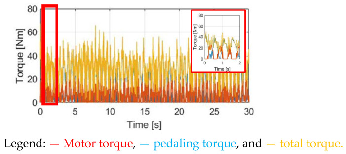
This paper proposes a novel torque measurement and control technique for cycling-assisted electric bikes (E-bikes) considering various external load conditions. For assisted E-bikes, the electromagnetic torque from the permanent magnet (PM) motor can be controlled to reduce the pedaling torque generated by the human rider. However, the overall cycling torque is affected by external loads, including the cyclist's weight, wind resistance, rolling resistance, and the road slope. With knowledge of these external loads, the motor torque can be adaptively controlled for these riding conditions. In this paper, key E-bike riding parameters are analyzed to find a suitable assisted motor torque. Four different motor torque control methods are proposed to improve the E-bike's dynamic response with minimal variation in acceleration. It is concluded that the wheel acceleration is important to determine the E-bike's synergetic torque performance. A comprehensive E-bike simulation environment is developed with MATLAB/Simulink to evaluate these adaptive torque control methods. In this paper, an integrated E-bike sensor hardware system is built to verify the proposed adaptive torque control.
Keywords: E-bike cycling quality; E-bike pedaling power; electric-assisted bicycle; permanent magnet motor; two-wheeler simulation.
Conflict of interest statement
The authors declare no conflict of interest.
Figures


Similar articles
-
Analyzing the impact of bicycle geometry and cargo loading on the rideability and safety of cargo bikes: An investigative study.Heliyon. 2024 Apr 11;10(8):e29524. doi: 10.1016/j.heliyon.2024.e29524. eCollection 2024 Apr 30. Heliyon. 2024. PMID: 38644891 Free PMC article.
-
Physical activity when riding an electric-assisted bicycle with and without cargo.Front Sports Act Living. 2023 Jun 30;5:1179043. doi: 10.3389/fspor.2023.1179043. eCollection 2023. Front Sports Act Living. 2023. PMID: 37457854 Free PMC article.
-
Risky riding: Naturalistic methods comparing safety behavior from conventional bicycle riders and electric bike riders.Accid Anal Prev. 2015 Sep;82:220-6. doi: 10.1016/j.aap.2015.05.016. Epub 2015 Jun 17. Accid Anal Prev. 2015. PMID: 26093098
-
Risk Riding Behaviors of Urban E-Bikes: A Literature Review.Int J Environ Res Public Health. 2019 Jun 28;16(13):2308. doi: 10.3390/ijerph16132308. Int J Environ Res Public Health. 2019. PMID: 31261838 Free PMC article. Review.
-
The impact of e-cycling on travel behaviour: A scoping review.J Transp Health. 2020 Dec;19:100910. doi: 10.1016/j.jth.2020.100910. Epub 2020 Aug 29. J Transp Health. 2020. PMID: 32904492 Free PMC article.
Cited by
-
Enhancing Urban Mobility with Self-Tuning Fuzzy Logic Controllers for Power-Assisted Bicycles in Smart Cities.Sensors (Basel). 2024 Feb 28;24(5):1552. doi: 10.3390/s24051552. Sensors (Basel). 2024. PMID: 38475087 Free PMC article.
References
-
- Lee J., Jiang J., Sun Y. Design and simulation of control systems for electric-assist bikes; Proceedings of the 2016 IEEE 11th Conference on Industrial Electronics and Applications (ICIEA); Hefei, China. 5–7 June 2016; pp. 1736–1740.
-
- Hunt K.J., Stone B., Negard N.O., Schauer T., Fraser M.H., Cathcart A.J., Ferrario C., Ward S.A., Grant S. Control strategies for integration of electric motor assist and functional electrical stimulation in paraplegic cycling: Utility for exercise testing and mobile cycling. IEEE Trans. Neural Syst. Rehabil. Eng. 2004;12:89–101. doi: 10.1109/TNSRE.2003.819955. - DOI - PubMed
-
- Zaghari B., Stuikys A., Weddell A.S., Beeby S. Efficient Energy Conversion in Electrically Assisted Bicycles Using a Switched Reluctance Machine Under Torque Control. IEEE Access. 2020;8:202401–202411. doi: 10.1109/ACCESS.2020.3036373. - DOI
-
- Palmieri G., Tiboni M., Legnani G. Analysis of the Upper Limitation of the Most Convenient Cadence Range in Cycling Using an Equivalent Moment Based Cost Function. Mathematics. 2020;8:1947. doi: 10.3390/math8111947. - DOI
LinkOut - more resources
Full Text Sources
Other Literature Sources
