. 2023 May 17;23(10):4826.
doi: 10.3390/s23104826.

Polyimide-On-Silicon 2D Piezoelectric Micromachined Ultrasound Transducer (PMUT) Array

Affiliations

Polyimide-On-Silicon 2D Piezoelectric Micromachined Ultrasound Transducer (PMUT) Array

Sanjog Vilas Joshi et al. Sensors (Basel). .

Abstract

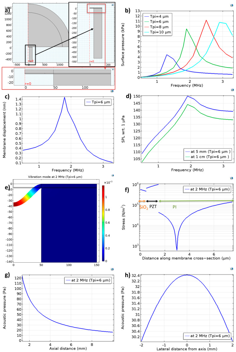
This paper presents a fully addressable 8 × 8 two-dimensional (2D) rigid piezoelectric micromachined ultrasonic transducer (PMUT) array. The PMUTs were fabricated on a standard silicon wafer, resulting in a low-cost solution for ultrasound imaging. A polyimide layer is used as the passive layer in the PMUT membranes on top of the active piezoelectric layer. The PMUT membranes are realized by backside deep reactive ion etching (DRIE) with an oxide etch stop. The polyimide passive layer enables high resonance frequencies that can be easily tuned by controlling the thickness of the polyimide. The fabricated PMUT with 6 µm polyimide thickness showed a 3.2 MHz in-air frequency with a 3 nm/V sensitivity. The PMUT has shown an effective coupling coefficient of 14% as calculated from the impedance analysis. An approximately 1% interelement crosstalk between the PMUT elements in one array is observed, which is at least a five-fold reduction compared to the state of the art. A pressure response of 40 Pa/V at 5 mm was measured underwater using a hydrophone while exciting a single PMUT element. A single-pulse response captured using the hydrophone suggested a 70% -6 dB fractional bandwidth for the 1.7 MHz center frequency. The demonstrated results have the potential to enable imaging and sensing applications in shallow-depth regions, subject to some optimization.

Keywords: PMUT; PZT; medical imaging; piezo-mems; piezoelectric thin films; ultrasound transducers.


Conflict of interest statement

The authors declare no conflict of interest.

Figures

Figure 1
Figure 1
(a) Schematic of a PMUT element (not to scale). (b) Two-dimensional PMUT array on the wafer. (c) Design of the demonstrated 8 × 8 array. (d) Zoomed-in view.
Figure 2
Figure 2
COMSOL simulation of a single PMUT element underwater: (a) Simulation geometry with zoomed−in views. The PMUT axis is indicated by r = 0, where r is the radial coordinate. (b) Simulation of surface pressure response with polyimide thickness as a parameter. For the PMUT element with 6 µm polyimide, (c) membrane displacement and (d) on−axis sound pressure level (SPL). Additionally, at 2 MHz, (e) vibration mode and (f) stress in the membrane along the axis of the PMUT, as well as (g) pressure decay with axial distance and (h) lateral pressure distribution at 5 mm.
Figure 3
Figure 3
Left: recipe of making PZT solution—(a) In a beaker, Zr and Ti precursors are refluxed with acetylacetone in stochiometric amounts. (b) In another beaker, 10% of excess Pb precursor is refluxed with acetic acid. (c) Mixing the two solutions is followed by the addition of a sol stabilizer and solvent. (d) Mixing and filtration of the solution in a stock bottle. Right: PZT thin film deposition procedure: spin coating, pyrolysis, and RTA are repeated 4 times in a cycle.
Figure 4
Figure 4
PMUT device fabrication process—(a) Oxide growth followed by deposition of the Pt as the bottom electrode. (b) Deposition and patterning of the PZT layer. (c) Patterning the top electrode. (d) Deposition and patterning of the polyimide passive layer. (e) Realizing the membrane via DRIE.
Figure 5
Figure 5
(a) XRD of the PZT. (b) P−E hysteresis loop of the PZT. (c) High−resolution optical microscope image of the high-frequency PMUT array membranes with 6 µm polyimide and 1 µm PZT. Zoomed−in view to the right. (d) The impedance of the single PMUT showing resonance (fr) and antiresonance frequencies (fa). (e) The impedance of the single PMUT underwater.
Figure 6
Figure 6
(a) Frequency response of a single PMUT with periodic chirp signal. (b) Underwater time domain response at 2 MHz with 2 V sinewave actuation. (c) Underwater measurement setup. Crosstalk (d) in air and (e) underwater.
Figure 7
Figure 7
(a) PMUT array glued to the PCB before wire-bonding. (b) Underwater hydrophone setup with a PMUT array wire−bonded to a PCB. (c) The response of single PMUT to 5−cycle square wave burst signal at 5 mm. (d) Eight PMUT elements together with 1 cycle pulse at 1 cm.
Figure 8
Figure 8
Characterization of PMUT receive response: (a) Signal measured via hydrophone. Signal measured via PMUT in response to (b) 1−cycle, (c) 5−cycle, and (d) 10−cycle pulses.

Similar articles

Cited by

References

    1. De Luca R., Forzoni L., Gelli F., Bamber J. An educational overview of ultrasound probe types and their fields of application. Arch. Acoust. 2021;46:3–15.
    1. Chen A.I.H., Wong L.L.P., Yeow J.T.W. Medical Imaging: Technology and Applications. CRC Press; Boca Raton, FL, USA: 2013. pp. 253–271.
    1. Shung K.K., Zippuro M. Ultrasonic transducers and arrays. IEEE Eng. Med. Biol. Mag. 1996;15:20–30. doi: 10.1109/51.544509. - DOI
    1. Eccardt P., Niederer K. Micromachined ultrasound transducers with improved coupling factors from a CMOS compatible process. Ultrasonics. 2000;38:774–780. doi: 10.1016/S0041-624X(99)00085-2. - DOI - PubMed
    1. Stephens D.N., Truong U.T., Nikoozadeh A., Oralkan Ö., Seo C.H., Cannata J., Dentinger A., Thomenius K., De La Rama A., Nguyen T., et al. First in vivo use of a capacitive micromachined ultrasound transducer array–based imaging and ablation catheter. J. Ultrasound Med. 2012;31:247–256. doi: 10.7863/jum.2012.31.2.247. - DOI - PMC - PubMed

LinkOut - more resources