

A System to Track Stent Location in the Human Body by Fusing Magnetometer and Accelerometer Measurements
- PMID: 37430804
- PMCID: PMC10222797
- DOI: 10.3390/s23104887
A System to Track Stent Location in the Human Body by Fusing Magnetometer and Accelerometer Measurements
Abstract
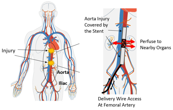
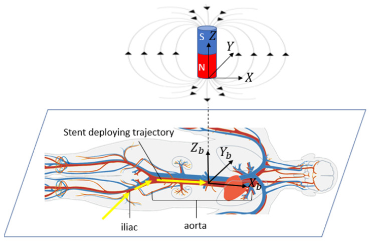
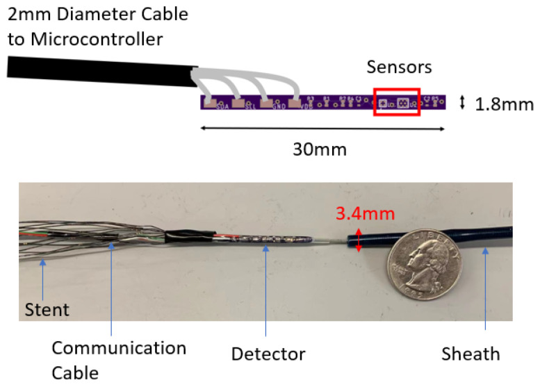
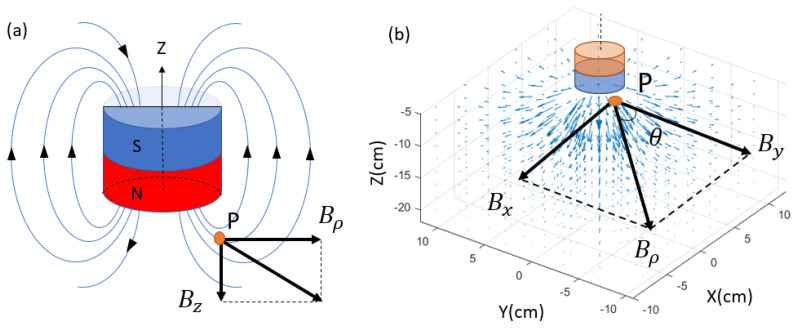
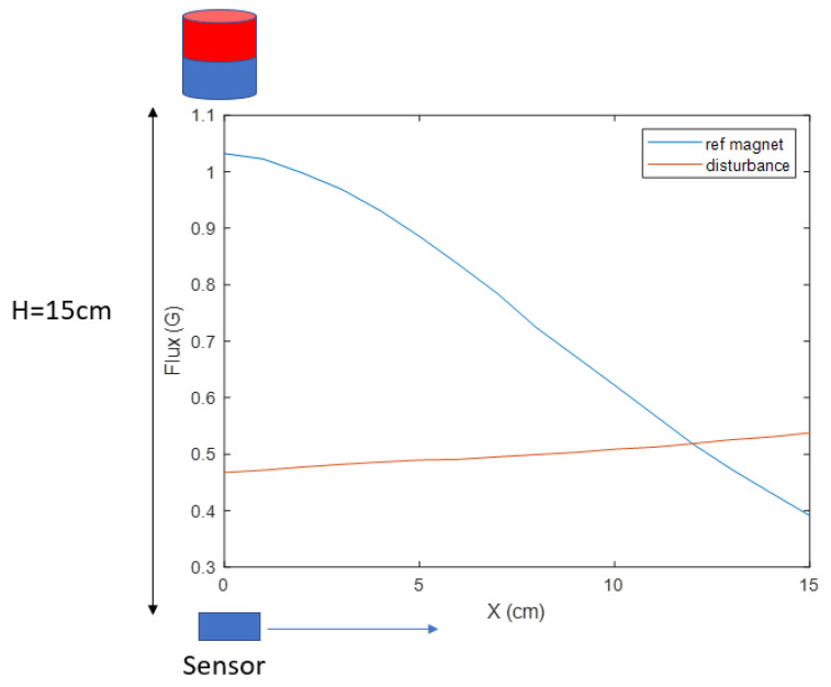
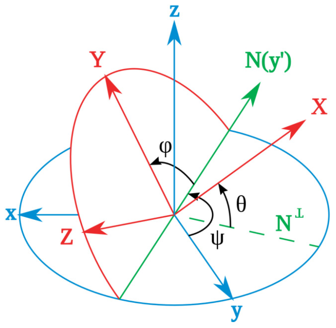
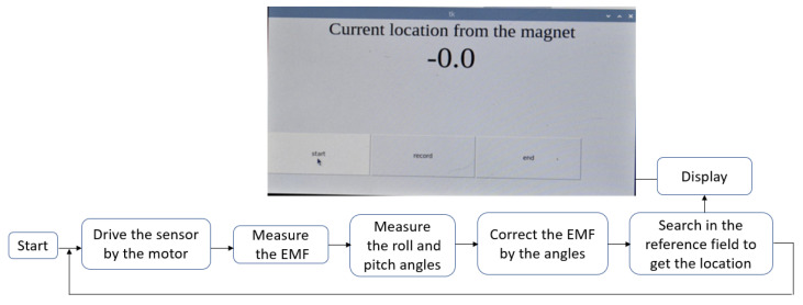
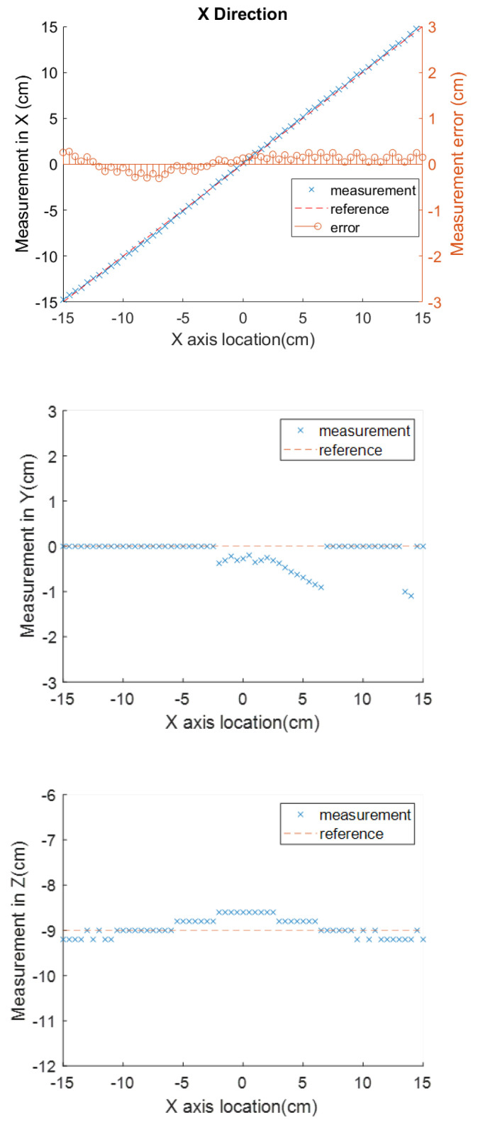
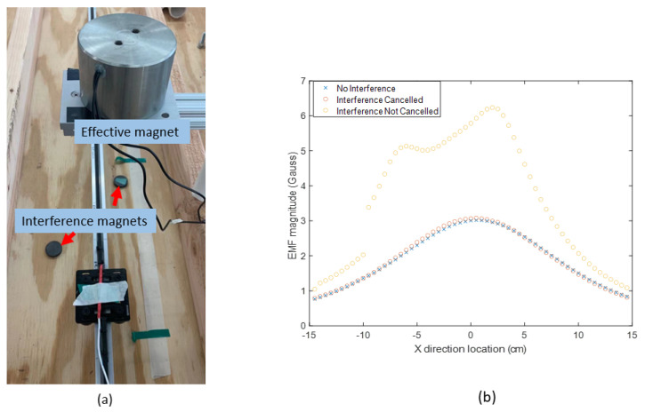
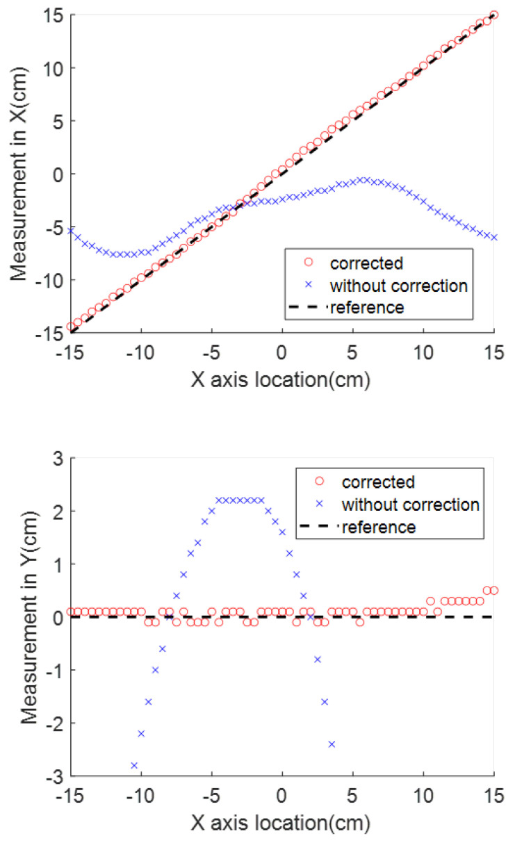
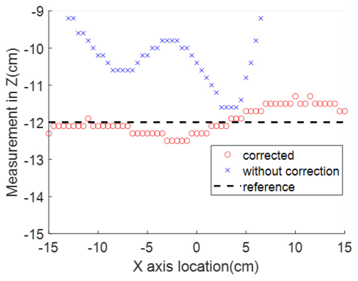
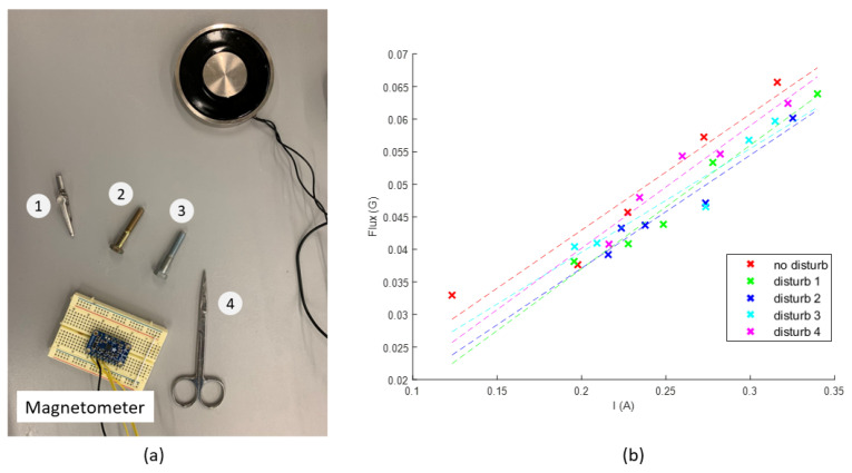
This paper will introduce a simple locating system to track a stent when it is deployed into a human artery. The stent is proposed to achieve hemostasis for bleeding soldiers on the battlefield, where common surgical imaging equipment such as fluoroscopy systems are not available. In the application of interest, the stent must be guided to the right location to avoid serious complications. The most important features are its relative accuracy and the ease by which it may be quickly set up and used in a trauma situation. The locating approach in this paper utilizes a magnet outside the human body as the reference and a magnetometer that will be deployed inside the artery with the stent. The sensor can detect its location in a coordinate system centered with the reference magnet. In practice, the main challenge is that the locating accuracy will be deteriorated by external magnetic interference, rotation of the sensor, and random noise. These causes of error are addressed in the paper to improve the locating accuracy and repeatability under various conditions. Finally, the system's locating performance will be validated in benchtop experiments, where the effects of the disturbance-eliminating procedures will be addressed.
Keywords: location tracking; magnetic field; magnetometer; sensor fusion; stent guidance.
Conflict of interest statement
The authors declare no conflict of interest.
Figures

Similar articles
-
A self calibrating, magnetic sensor approach accurately positions an aortic damage control stent in a porcine model.Trauma Surg Acute Care Open. 2023 Dec 8;8(1):e001220. doi: 10.1136/tsaco-2023-001220. eCollection 2023. Trauma Surg Acute Care Open. 2023. PMID: 38089400 Free PMC article.
-
C-arm angle measurement with accelerometer for brachytherapy: an accuracy study.Int J Comput Assist Radiol Surg. 2014 Jan;9(1):137-44. doi: 10.1007/s11548-013-0918-3. Epub 2013 Jul 3. Int J Comput Assist Radiol Surg. 2014. PMID: 23820762
-
Stereotactic endovascular aortic navigation with a novel ultrasonic-based three-dimensional localization system.J Vasc Surg. 2013 Jun;57(6):1637-44. doi: 10.1016/j.jvs.2012.09.078. Epub 2013 Jan 29. J Vasc Surg. 2013. PMID: 23375138
-
[Absorbable coronary stents. New promising technology].Herz. 2007 Jun;32(4):308-19. doi: 10.1007/s00059-007-2995-y. Herz. 2007. PMID: 17607538 Review. German.
-
Stent-graft treatment of trauma to the supra-aortic arteries. A review.J Cardiovasc Surg (Torino). 2007 Oct;48(5):537-49. J Cardiovasc Surg (Torino). 2007. PMID: 17989623 Review.
Cited by
-
Effects of Sampling Frequency on Human Activity Recognition with Machine Learning Aiming at Clinical Applications.Sensors (Basel). 2025 Jun 17;25(12):3780. doi: 10.3390/s25123780. Sensors (Basel). 2025. PMID: 40573667 Free PMC article.
-
A self calibrating, magnetic sensor approach accurately positions an aortic damage control stent in a porcine model.Trauma Surg Acute Care Open. 2023 Dec 8;8(1):e001220. doi: 10.1136/tsaco-2023-001220. eCollection 2023. Trauma Surg Acute Care Open. 2023. PMID: 38089400 Free PMC article.
References
-
- Wortham L. Hemorrhage control in the battlefield: Role of new hemostatic agent. Mil. Med. 2005;170:63–69. - PubMed
-
- Kragh J.F., Murphy C., Dubick M.A., Baer D.G., Johnson J., Blackbourne L.H. New tourniquet device concepts for battlefield hemorrhage control. US Army Med. Dep. J. 2011:38–48. - PubMed
-
- Kenawy D.M., Zhang Y., Elsisy M., Chun Y., Garcia-Neuer M., Abdel-Rasoul M., Clark W., Tillman B. A Magnetic Sensor-equipped Retrievable Aortic Rescue Stent Graft for Noncompressible Torso Hemorrhage. J. Vasc. Surg. 2022;75:e319–e320. doi: 10.1016/j.jvs.2022.03.747. - DOI
MeSH terms
Grants and funding
LinkOut - more resources
Full Text Sources
