. 2023 Jul 5;24(13):11102.
doi: 10.3390/ijms241311102.

Composite Fibrin/Carbon Microfiber Implants for Bridging Spinal Cord Injury: A Translational Approach in Pigs

Affiliations

Composite Fibrin/Carbon Microfiber Implants for Bridging Spinal Cord Injury: A Translational Approach in Pigs

Alexandra Alves-Sampaio et al. Int J Mol Sci. .

Abstract

Biomaterials may enhance neural repair after spinal cord injury (SCI) and testing their functionality in large animals is essential to achieve successful clinical translation. This work developed a porcine contusion/compression SCI model to investigate the consequences of myelotomy and implantation of fibrin gel containing biofunctionalized carbon microfibers (MFs). Fourteen pigs were distributed in SCI, SCI/myelotomy, and SCI/myelotomy/implant groups. An automated device was used for SCI. A dorsal myelotomy was performed on the lesion site at 1 day post-injury for removing cloths and devitalized tissue. Bundles of MFs coated with a conducting polymer and cell adhesion molecules were embedded in fibrin gel and used to bridge the spinal cord cavity. Reproducible lesions of about 1 cm in length were obtained. Myelotomy and lesion debridement caused no further neural damage compared to SCI alone but had little positive effect on neural regrowth. The MFs/fibrin gel implant facilitated axonal sprouting, elongation, and alignment within the lesion. However, the implant also increased lesion volume and was ineffective in preventing fibrosis, thus precluding functional neural regeneration. Our results indicate that myelotomy and lesion debridement can be advantageously used for implanting MF-based scaffolds. However, the implants need refinement and pharmaceuticals will be necessary to limit scarring.

Keywords: biomaterial; compression; conducting polymer; contusion; microfiber; myelotomy; pig; porcine; regeneration; spinal cord injury.


Conflict of interest statement

J.E.C.-C. and A.A.-S. have shares in Spinal Cord Technologies S.L., a spin-off company of the Hospital Nacional de Parapléjicos in Toledo, Spain. J.E. Collazos-Castro is inventor in patent ESP201231969 regarding conducting-polymer-coated carbon MFs, and together with A. Alves-Sampaio, he is the co-inventor in the patent application P202230626 on fibrin/MFs scaffolds. The funders had no role in the design of the study; in the collection, analyses, or interpretation of data; in the writing of the manuscript; or in the decision to publish the results.

Figures
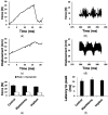
Figure 1
Figure 1
Biomechanical parameters of the injury. (a) Example of force development during the initial impact (contusion phase). The contact of the impactor with the spinal cord occurred at time = 0 and the peak force (set at 25 N) was reached about 16 ms later. (b) Example of force recorded during the compression phase. The average force was close to 10 N but oscillated between 5 and 15 N due to spinal cord movements with breathing. (c) Tissue displacement during the contusion phase (shown in (a)). (d) Tissue displacement during the compression phase shown in (b). Oscillations in force and displacement occurred in phase with respiratory movements. (e) Forces for each injury phase and treatment group. (f) Latency to peak force for each treatment group. (g) Tissue displacement for each treatment group. (h) Linear regression for latency to peak force and tissue displacement during the contusion phase, including data from all groups. Data in (eg) are represented as the mean ± standard error.
Figure 1
Figure 1
Biomechanical parameters of the injury. (a) Example of force development during the initial impact (contusion phase). The contact of the impactor with the spinal cord occurred at time = 0 and the peak force (set at 25 N) was reached about 16 ms later. (b) Example of force recorded during the compression phase. The average force was close to 10 N but oscillated between 5 and 15 N due to spinal cord movements with breathing. (c) Tissue displacement during the contusion phase (shown in (a)). (d) Tissue displacement during the compression phase shown in (b). Oscillations in force and displacement occurred in phase with respiratory movements. (e) Forces for each injury phase and treatment group. (f) Latency to peak force for each treatment group. (g) Tissue displacement for each treatment group. (h) Linear regression for latency to peak force and tissue displacement during the contusion phase, including data from all groups. Data in (eg) are represented as the mean ± standard error.
Figure 2
Figure 2
General assessment of the lesion at 30 days post-lesion (DPL). (ac) 50 μm spinal cord sections from animals with control SCI (a), SCI + myelotomy (b), and SCI + myelotomy + implant (c), processed for cresyl violet (left) or eriochrome cyanine (right) staining. The lesion area is delineated in red. Numbers indicate the following: 1, spared white matter (blue) on one side of the spinal cord; 2, lesion cavities; 3, lesion trabeculae; and 4, dense meningeal scar in the most severely injured side. (d) Quantification of lesion volume (upper panel) and cavitation and tissue within the lesion for the different treatment groups. Data represent the mean ± standard error. Statistically significant differences are indicated with asterisks. * p < 0.05. Scale bar, 2 mm.
Figure 3
Figure 3
Immunohistochemical assessment of the lesion at 30 DPL. (a) 10-μm spinal cord sections representative for the different treatment groups, immunostained for the cell markers indicated in the panels. 1–3: Double fluorescent staining for fibrotic tissue (PDGFRβ, green) and axons (neurofilament, NF, red). The regions in squares are magnified below, including a view of only NF for a better appreciation of axons within the lesion. Note that in the control case, most NF-positive cellular processes are fragmented axons not yet removed from the lesion at the time of tissue fixation, whereas in the implanted animal, numerous axons grew associated with migrating PDGFRβ-expressing cells. 4–6: Spinal cord sections showing double immunostaining for serotonergic axons (green) and astrocytes (GFAP, red). The rostral border of the lesion is on the left. (b,c) Quantification of stained cellular processes for the different treatment groups. Data represent the mean ± standard error. Statistically significant differences are indicated with asterisks.* p < 0.05. Scale bars: 1–3, 2 mm; square magnifications in i–iii, 500 μm; 4–6, 500 μm.
Figure 3
Figure 3
Immunohistochemical assessment of the lesion at 30 DPL. (a) 10-μm spinal cord sections representative for the different treatment groups, immunostained for the cell markers indicated in the panels. 1–3: Double fluorescent staining for fibrotic tissue (PDGFRβ, green) and axons (neurofilament, NF, red). The regions in squares are magnified below, including a view of only NF for a better appreciation of axons within the lesion. Note that in the control case, most NF-positive cellular processes are fragmented axons not yet removed from the lesion at the time of tissue fixation, whereas in the implanted animal, numerous axons grew associated with migrating PDGFRβ-expressing cells. 4–6: Spinal cord sections showing double immunostaining for serotonergic axons (green) and astrocytes (GFAP, red). The rostral border of the lesion is on the left. (b,c) Quantification of stained cellular processes for the different treatment groups. Data represent the mean ± standard error. Statistically significant differences are indicated with asterisks.* p < 0.05. Scale bars: 1–3, 2 mm; square magnifications in i–iii, 500 μm; 4–6, 500 μm.
Figure 4
Figure 4
Axonal growth and guidance supported by microfibers (MFs) implanted in the porcine spinal cord. Transmitted light imaging (top) enabled visualization of the MFs, whereas fluorescent immunostaining for neurofilament (red, middle) allowed the identification of axons. The merged image at (bottom) illustrates fasciculated axons penetrating the lesion aided by the MFs, which effectively bridged the spinal cord cavity. Scale bar, 100 μm.
Figure 5
Figure 5
Behavioral outcomes after SCI. (a) Photograph at 1 DPL illustrating the typical posture of the animals with the paralyzed hindlimbs. (b) Behavioral recovery as assessed using the PTIBS scale [36]. There was little recovery with no significant differences between the treatment groups during the four weeks of follow-up.
Figure 6
Figure 6
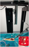
Custom-designed impactor device and positioning framework. Intraoperative photograph illustrating the device and the framework with the pig ready for SCI. (1,2) Forceps assembled on a track to immobilize the spine. (3) Box containing the stepping motor, the position sensor, and the impactor rack. The box is mounted on a rail with movement on the X, Y, and Z axes (46). (7) Cables communicating the sensors and the motor with the controller. (8) Rack with the force sensor and impacting tip, aligned to the spinal cord. (9) Magnified view of the force sensor and impacting tip (8 mm diameter flat circular head) close to the porcine spinal cord.
Figure 7
Figure 7
Implantation of fibrin/MFs bundles in the porcine spinal cord. Intraoperative photographs of the surgical procedure. (a) Dorsal view of the lesion site at 1 DPL. A durotomy is performed in the midline. (b) Hemorrhagic liquid and devitalized tissue protrudes through the incision of the dura matter. (c) Aspect of the cavity after irrigating the lesion with saline solution and removing blood clots and tissue adherences. (d,e) Accommodation of fibrin/MFs bundles into the cavity. (f) Suture of the dura mater. Scale bar, 5 mm.

Similar articles

Cited by

References

    1. Collazos-Castro J.E. Handbook of Innovations in Central Nervous System Regenerative Medicine. Elsevier; Amsterdam, The Netherlands: 2020. Biomaterial-based systems as biomimetic agents in the repair of the central nervous system; pp. 259–289.
    1. Hurtado A., Cregg J.M., Wang H.B., Wendell D.F., Oudega M., Gilbert R.J., McDonald J.W. Robust CNS regeneration after complete spinal cord transection using aligned poly-L-lactic acid microfibers. Biomaterials. 2011;32:6068–6079. doi: 10.1016/j.biomaterials.2011.05.006. - DOI - PMC - PubMed
    1. Alves-Sampaio A., García-Rama C., Collazos-Castro J.E. Biofunctionalized PEDOT-coated microfibers for the treatment of spinal cord injury. Biomaterials. 2016;89:98–113. doi: 10.1016/j.biomaterials.2016.02.037. - DOI - PubMed
    1. Guest J.D., Moore S.W., Aimetti A.A., Kutikov A.B., Santamaria A.J., Hofstetter C.P., Ropper A.E., Theodore N., Ulich T.R., Layer R.T. Internal decompression of the acutely contused spinal cord: Differential effects of irrigation only versus biodegradable scaffold implantation. Biomaterials. 2018;185:284–300. doi: 10.1016/j.biomaterials.2018.09.025. - DOI - PubMed
    1. Dumont C.M., Carlson M.A., Munsell M.K., Ciciriello A.J., Strnadova K., Park J., Cummings B.J., Anderson A.J., Shea L.D. Aligned hydrogel tubes guide regeneration following spinal cord injury. Acta Biomater. 2019;86:312–322. doi: 10.1016/j.actbio.2018.12.052. - DOI - PMC - PubMed

Grants and funding