. 2023 Apr;122(17):10.1063/5.0145077.
doi: 10.1063/5.0145077.

Trap-Integrated Superconducting Nanowire Single-Photon Detectors with Improved RF Tolerance for Trapped-Ion Qubit State Readout

Affiliations

Trap-Integrated Superconducting Nanowire Single-Photon Detectors with Improved RF Tolerance for Trapped-Ion Qubit State Readout

Benedikt Hampel et al. Appl Phys Lett. 2023 Apr.

Abstract

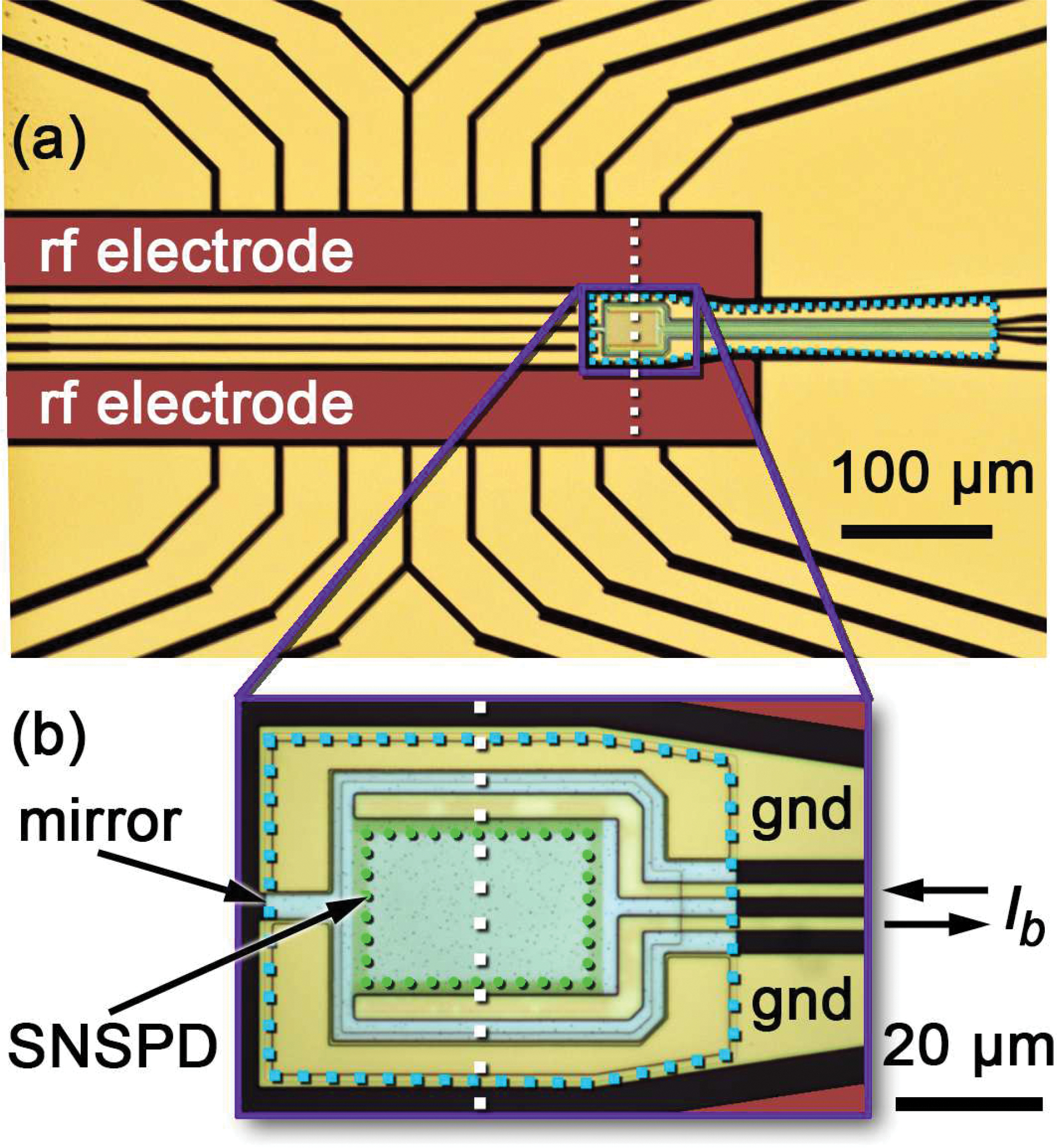
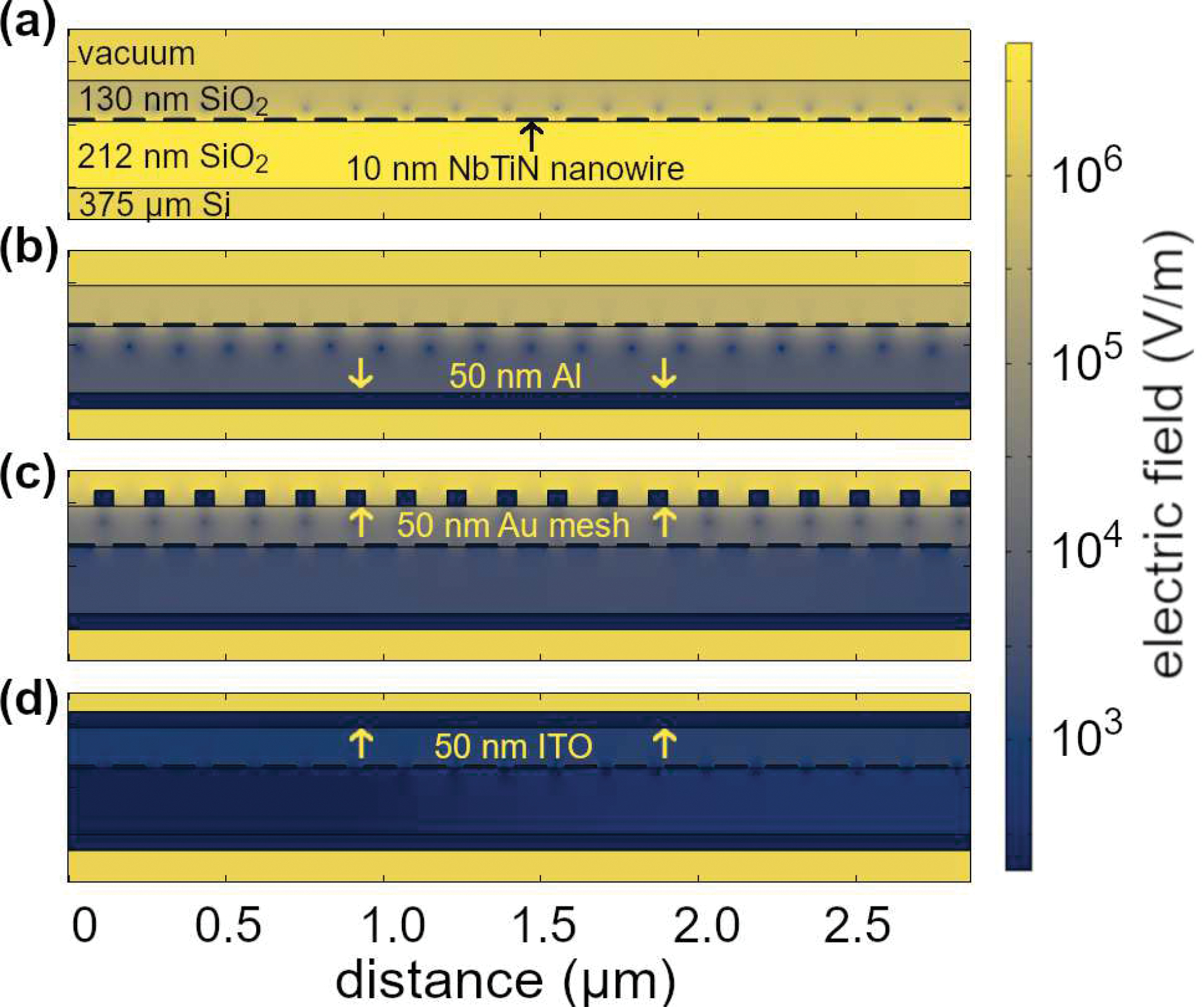
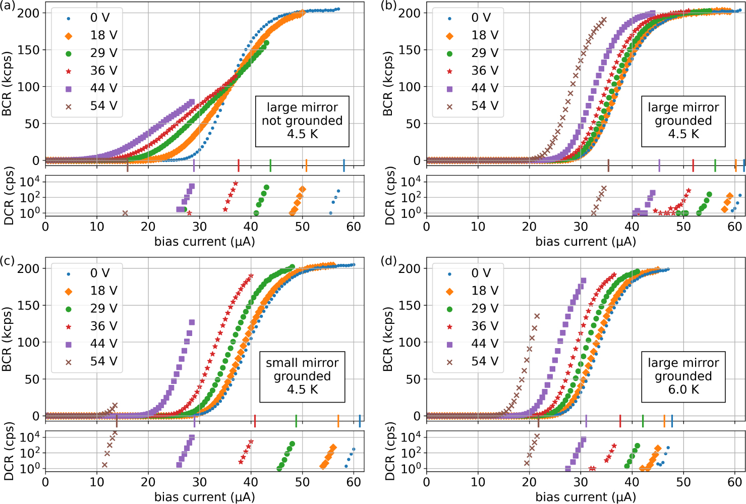
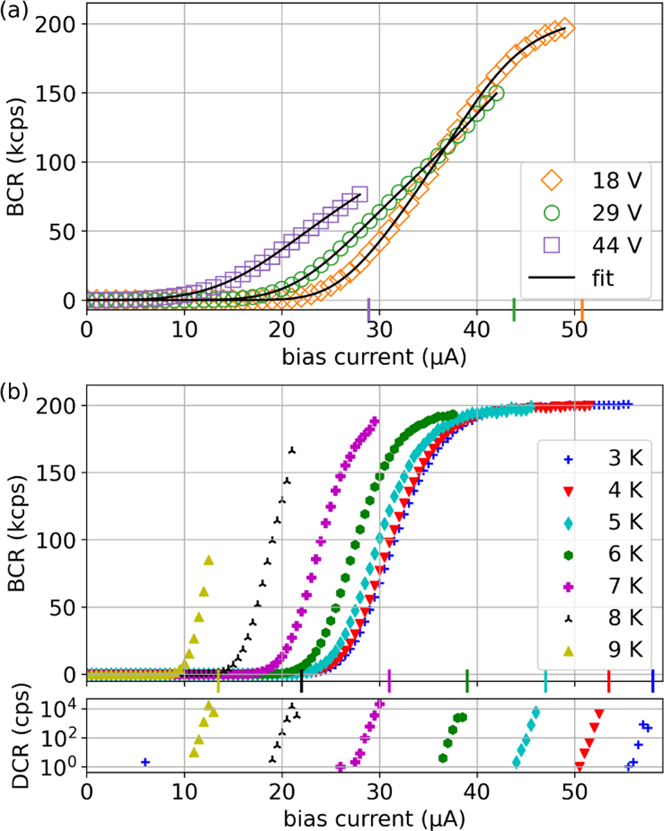
State readout of trapped-ion qubits with trap-integrated detectors can address important challenges for scalable quantum computing, but the strong rf electric fields used for trapping can impact detector performance. Here, we report on NbTiN superconducting nanowire single-photon detectors (SNSPDs) employing grounded aluminum mirrors as electrical shielding that are integrated into linear surface-electrode rf ion traps. The shielded SNSPDs can be operated at applied rf trapping potentials of up to 54 Vpeak at 70 MHz and temperatures of up to 6 K, with a maximum system detection efficiency of 68 %. This performance should be sufficient to enable parallel high-fidelity state readout of a wide range of trapped ion species in typical cryogenic apparatus.


Conflict of interest statement

Conflict of Interest The authors have no conflicts to disclose.

Figures

FIG. 1:
FIG. 1:
Photomicrograph of the linear ion trap with integrated SNSPD. The rf trapping potentials are applied to the labeled and false-colored rf electrodes. All other non-SNSPD electrodes are used for dc trapping potentials. The magnified inset (b) shows a trap design where the SNSPD is on top of a small aluminum mirror, while a larger aluminum mirror spanning the region beneath the leads of the SNSPD can be seen in a different trap design shown in panel (a). Both mirrors appear light blue in the gaps between gold electrodes and are surrounded by a light blue dotted line, while the black gaps show the substrate. The green dotted line in (b) borders the active area of the SNSPD. The white dashed lines indicate the plane of the 2D simulations in Fig. 2. The bias current Ib is applied to the leads of the SNSPD. The electrodes labeled “gnd” are electrically connected to the mirror and can be connected to ground.
FIG. 2:
FIG. 2:
Numerically simulated electric field amplitude from an rf potential of 100 Vpeak at 70 MHz applied to the rf electrodes of the ion trap, viewed for a small cross-section of the SNSPD and for different shielding configurations. The thicknesses of the various material layers are shown on the figure. (a) SNSPD nanowire embedded in SiO2 without shielding. (b) Grounded aluminum mirror under the nanowire. (c) Grounded gold mesh on top of the stack in addition to the grounded aluminum mirror. (d) Grounded ITO layer instead of the gold mesh.
FIG. 3:
FIG. 3:
Bright count rate (BCR) and dark count rate (DCR) in counts per second (cps) as a function of bias current for different rf voltage peak amplitudes on the ion trap at a temperature of 4.5 K for devices with a large mirror that is (a) not connected to ground and (b) connected to ground. Comparison to device with (c) a smaller grounded mirror at 4.5 K and (d) the same device as in (b) operated at 6 K. The switching currents for each value of applied rf are indicated with correspondingly colored vertical markers on the horizontal axes. BCR values shown are corrected for DCR. DCR is plotted on logarithmic vertical axes.
FIG. 4:
FIG. 4:
Bright count rate (BCR) and dark count rate (DCR) in counts per second (cps) as a function of bias current. (a) Curve fits for an induced rf current model to the data in Fig. 3(a). (b) BCR and DCR vs. Ib without rf drive at different temperatures for a trap-integrated SNSPD. The switching currents are indicated with markers on the horizontal axis.

References

    1. Dehmelt HG, “Monoion oscillator as potential ultimate laser frequency standard,” IEEE Transactions on Instrumentation and Measurement IM-31, 83–87 (1982).
    1. Wineland DJ, Monroe C, Itano WM, Leibfried D, King BE, and Meekhof DM, “Experimental issues in coherent quantum-state manipulation of trapped atomic ions,” Journal of Research of the National Institute of Standards and Technology 103, 259–328 (1998). - PMC - PubMed
    1. Kielpinski D, Monroe C, and Wineland DJ, “Architecture for a large-scale ion-trap quantum computer.” Nature 417, 709–11 (2002). - PubMed
    1. Monroe C and Kim J, “Scaling the Ion Trap Quantum Processor,” Science 339, 1164–1169 (2013). - PubMed
    1. Bruzewicz CD, Chiaverini J, McConnell R, and Sage JM, “Trapped-ion quantum computing: Progress and challenges,” Applied Physics Reviews 6, 021314 (2019).