

Nanoporous electroporation needle for localized intracellular delivery in deep tissues
- PMID: 37476054
- PMCID: PMC10354752
- DOI: 10.1002/btm2.10418
Nanoporous electroporation needle for localized intracellular delivery in deep tissues
Abstract
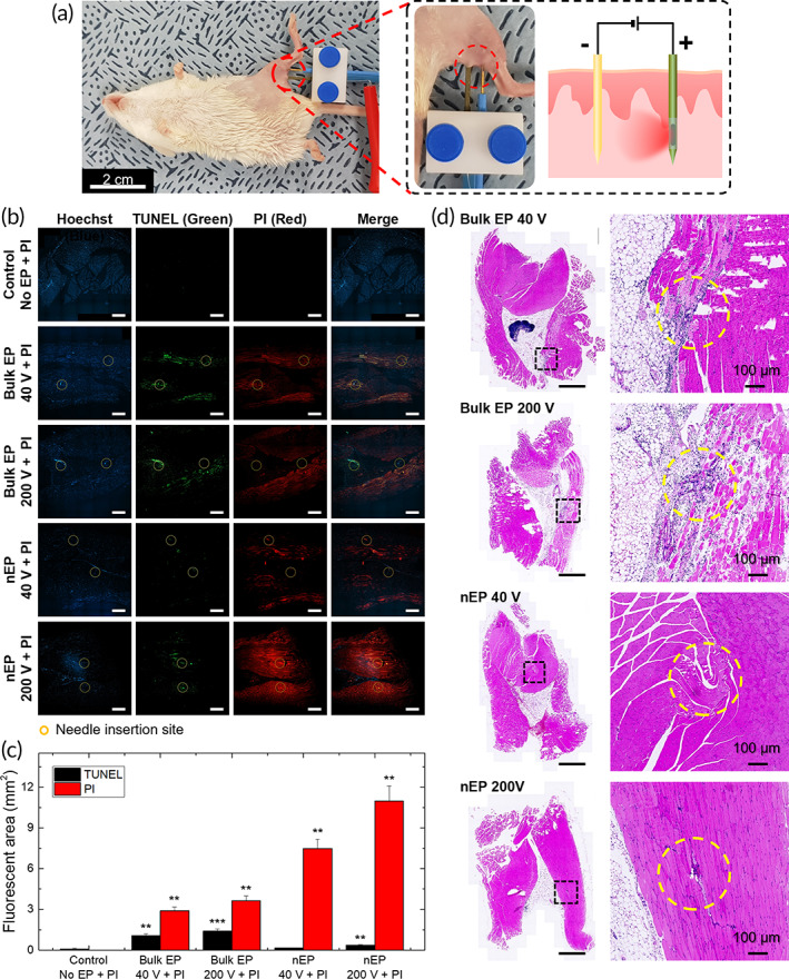
The exogenous control of intracellular drug delivery has been shown to improve the overall efficacy of therapies by reducing nonspecific off-target toxicity. However, achieving a precise on-demand dosage of a drug in deep tissues with minimal damage is still a challenge. In this study, we report an electric-pulse-driven nanopore-electroporation (nEP) system for the localized intracellular delivery of a model agent in deep tissues. Compared with conventional bulk electroporation, in vitro nEP achieved better transfection efficiency (>60%) with a high cell recovery rate (>95%) under a nontoxic low electroporation condition (40 V). Furthermore, in vivo nEP using a nanopore needle electrode with a side drug-releasing compartment offered better control over the dosage release, time, and location of propidium iodide, which was used as a model agent for intracellular delivery. In a pilot study using experimental animals, the nEP system exhibited two times higher transfection efficiency of propidium iodide in the thigh muscle tissue, while minimizing tissue damage (<20%) compared to that of bulk electroporation. This tissue-penetrating nEP platform can provide localized, safe, and effective intracellular delivery of diverse therapeutics into deep tissues in a controlled manner.
Keywords: electric pulse‐driven drug delivery; electroporation; intracellular delivery; nanopore membrane.
© 2022 The Authors. Bioengineering & Translational Medicine published by Wiley Periodicals LLC on behalf of American Institute of Chemical Engineers.
Conflict of interest statement
The authors declare that they have no conflict of interest.
Figures


Similar articles
-
Microtrap array on a chip for localized electroporation and electro-gene transfection.Bioelectrochemistry. 2022 Oct;147:108197. doi: 10.1016/j.bioelechem.2022.108197. Epub 2022 Jun 28. Bioelectrochemistry. 2022. PMID: 35810498
-
Cell membrane damage and cargo delivery in nano-electroporation.Nanoscale. 2023 Feb 23;15(8):4080-4089. doi: 10.1039/d2nr05575a. Nanoscale. 2023. PMID: 36744418
-
Nontoxic nanopore electroporation for effective intracellular delivery of biological macromolecules.Proc Natl Acad Sci U S A. 2019 Apr 16;116(16):7899-7904. doi: 10.1073/pnas.1818553116. Epub 2019 Mar 28. Proc Natl Acad Sci U S A. 2019. PMID: 30923112 Free PMC article.
-
High Throughput and Highly Controllable Methods for In Vitro Intracellular Delivery.Small. 2020 Dec;16(51):e2004917. doi: 10.1002/smll.202004917. Epub 2020 Nov 25. Small. 2020. PMID: 33241661 Free PMC article. Review.
-
Micro-/nano-electroporation for active gene delivery.Curr Pharm Des. 2015;21(42):6081-8. doi: 10.2174/1381612821666151027152121. Curr Pharm Des. 2015. PMID: 26503150 Review.
Cited by
-
Liver-tumor mimics as a potential translational framework for planning and testing irreversible electroporation with multiple electrodes.Bioeng Transl Med. 2023 Nov 23;9(1):e10607. doi: 10.1002/btm2.10607. eCollection 2024 Jan. Bioeng Transl Med. 2023. PMID: 38193113 Free PMC article.
-
Advanced technologies for biomedical applications by emerging researchers in Asia-Pacific.Bioeng Transl Med. 2023 Nov 19;8(6):e10621. doi: 10.1002/btm2.10621. eCollection 2023 Nov. Bioeng Transl Med. 2023. PMID: 38023727 Free PMC article. No abstract available.
-
Advancements in Skin-Mediated Drug Delivery: Mechanisms, Techniques, and Applications.Adv Healthc Mater. 2024 Mar;13(7):e2302375. doi: 10.1002/adhm.202302375. Epub 2023 Dec 7. Adv Healthc Mater. 2024. PMID: 38009520 Free PMC article. Review.
References
-
- Chien YW. Novel drug delivery systems. Drugs Pharm Sci. 1992;50:797.
-
- Langer R. Drug delivery and targeting. Nature. 1998;392:5‐10. - PubMed
LinkOut - more resources
Full Text Sources
