

Experimental Characterization of Composite-Printed Materials for the Production of Multirotor UAV Airframe Parts
- PMID: 37512334
- PMCID: PMC10384317
- DOI: 10.3390/ma16145060
Experimental Characterization of Composite-Printed Materials for the Production of Multirotor UAV Airframe Parts
Abstract
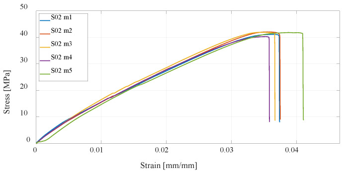
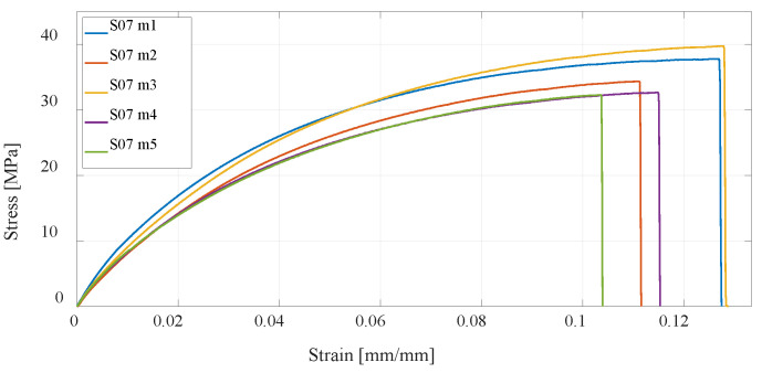
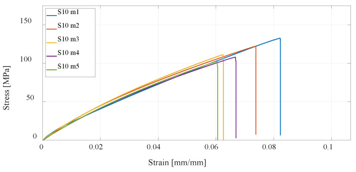
In this paper, the characterization of 3D-printed materials that are considered in the design of multirotor unmanned aerial vehicles (UAVs) for specialized purposes was carried out. The multirotor UAV system is briefly described, primarily from the aspect of system dynamics, considering that the airframe parts connect the UAV components, including the propulsion configuration, into a functional assembly. Three additive manufacturing (AM) technologies were discussed, and a brief overview was provided of selective laser sintering (SLS), fused deposition modeling (FDM), and continuous fiber fabrication (CFF). Using hardware and related software, 12 series of specimens were produced, which were experimentally tested utilizing a quasi-static uniaxial tensile test. The results of the experimental tests are provided graphically with stress-strain diagrams. In this work, the focus is on CFF technology and the testing of materials that will be used in the production of mechanically loaded airframe parts of multirotor UAVs. The experimentally obtained values of the maximum stresses were compared for different technologies. For the considered specimens manufactured using FDM and SLS technology, the values are up to 40 MPa, while for the considered CFF materials and range of investigated specimens, it is shown that it can be at least four times higher. By increasing the proportion of fibers, these differences increase. To be able to provide a wider comparison of CFF technology and investigated materials with aluminum alloys, the following three-point flexural and Charpy impact tests were selected that fit within this framework for experimental characterization.
Keywords: additive manufacturing; continuous fiber fabrication; fiberglass reinforcement; material experimental characterization; multirotor UAV airframe parts; uniaxial tensile test.
Conflict of interest statement
The authors declare no conflict of interest.
Figures


References
-
- Sharma S.K., Saxena K.K., Dixit A.K., Singh R., Mohammed K.A. Role of additive manufacturing and various reinforcements in MMCs related to biomedical applications. Adv. Mater. Process. Technol. 2022:1–18. doi: 10.1080/2374068X.2022.2122005. - DOI
-
- Ahmad M.N., Tarmeze A.A., Rasib A.H.A. Capability of 3D Printing Technology in Producing Molar Teeth Prototype. Int. J. Eng. Appl. (IREA) 2020;8:64. doi: 10.15866/irea.v8i2.17949. - DOI
-
- Morgan J.L., Gergel S.E., Coops N.C. Aerial Photography: A Rapidly Evolving Tool for Ecological Management. Bioscience. 2010;60:47–59. doi: 10.1525/bio.2010.60.1.9. - DOI
-
- Yeom S., Cho I.-J. Detection and Tracking of Moving Pedestrians with a Small Unmanned Aerial Vehicle. Appl. Sci. 2019;9:3359. doi: 10.3390/app9163359. - DOI
-
- Kim J., Kim S., Ju C., Son H.I. Unmanned Aerial Vehicles in Agriculture: A Review of Perspective of Platform, Control, and Applications. IEEE Access. 2019;7:105100–105115. doi: 10.1109/ACCESS.2019.2932119. - DOI
Grants and funding
LinkOut - more resources
Full Text Sources
