. 2023 Jul 31;14(1):4585.
doi: 10.1038/s41467-023-39921-4.

Conformational changes in the essential E. coli septal cell wall synthesis complex suggest an activation mechanism

Affiliations

Conformational changes in the essential E. coli septal cell wall synthesis complex suggest an activation mechanism

Brooke M Britton et al. Nat Commun. .

Abstract

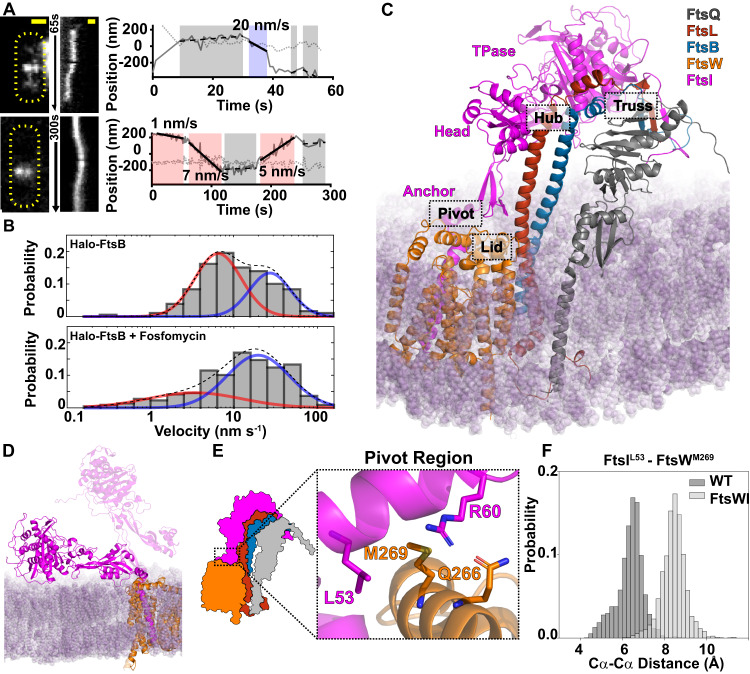
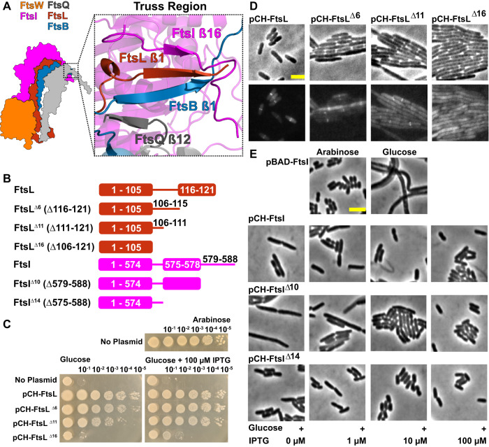
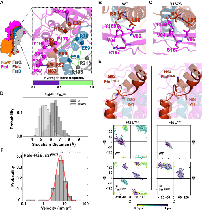
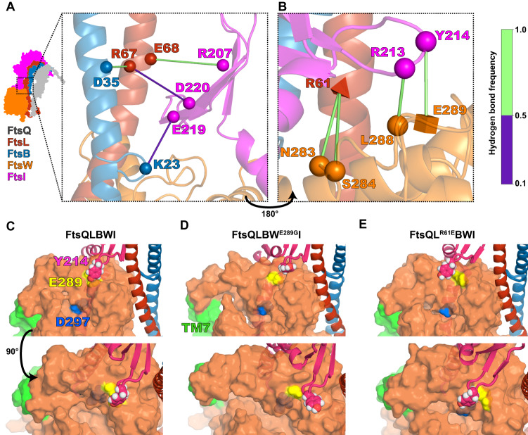
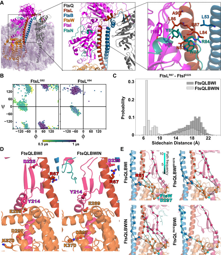
The bacterial divisome is a macromolecular machine composed of more than 30 proteins that controls cell wall constriction during division. Here, we present a model of the structure and dynamics of the core complex of the E. coli divisome, supported by a combination of structure prediction, molecular dynamics simulation, single-molecule imaging, and mutagenesis. We focus on the septal cell wall synthase complex formed by FtsW and FtsI, and its regulators FtsQ, FtsL, FtsB, and FtsN. The results indicate extensive interactions in four regions in the periplasmic domains of the complex. FtsQ, FtsL, and FtsB support FtsI in an extended conformation, with the FtsI transpeptidase domain lifted away from the membrane through interactions among the C-terminal domains. FtsN binds between FtsI and FtsL in a region rich in residues with superfission (activating) and dominant negative (inhibitory) mutations. Mutagenesis experiments and simulations suggest that the essential domain of FtsN links FtsI and FtsL together, potentially modulating interactions between the anchor-loop of FtsI and the putative catalytic cavity of FtsW, thus suggesting a mechanism of how FtsN activates the cell wall synthesis activities of FtsW and FtsI.


Conflict of interest statement

The authors declare no competing interests.

Figures

Fig. 1
Fig. 1. Characterization and modeling of the E. coli FtsQLBWI complex.
A, B Single-molecule tracking of Halo-FtsB suggests that FtsQLB remain in complex with FtsWI on both the fast-moving FtsZ-track and the slow-moving sPG synthesis track. A Two representative Halo-FtsB expressing cells with the maximum fluorescence intensity projection images (left), kymographs of fluorescence line scans at the midcell (middle), and unwrapped one-dimensional positions of the corresponding Halo-FtsB molecule along the circumference (solid gray line) and long axis (dotted gray line) of the cell were shown. Measured velocity of each segment and the corresponding classification (fast-moving, cyan; slow-moving, pink; stationary, gray) are labeled in the trajectory panels. Scale bar 500 nm. Similar images were observed in N > 100 cells. B Distribution of velocities of single Halo-FtsB molecules exhibiting directional motion in wild-type E. coli cells grown in minimal media in the absence (top) of fosfomycin was best fit with two moving populations, one slow (red) and one fast (blue). A dashed line indicates the summed probability. In the presence of fosfomycin that inhibits cell wall synthesis (bottom), the slow-moving population (red) is drastically reduced. These dynamics behaviors are similar to those of FtsW or FtsI. C Modeled structure of E. coli FtsQLBWI within a POPE bilayer (purple) in the last frame of a 1-μs MD simulation. The complex consists of FtsQ 20–276 (gray), FtsL 1–121 (red), FtsB 1–113 (blue), FtsW 46–414 (orange), and FtsI 19–588 (magenta). The FtsI TPase, head and anchor domains are labeled in magenta text. The four interface regions—Pivot, Truss, Hub, and Lid—are highlighted in dashed boxes. D In the absence of FtsQLB, FtsI (magenta) collapses to the membrane (purple) at the end of the 1-μs MD simulation. The position of FtsI at the beginning of the simulation (transparent magenta) is shown for comparison. E Zoomed-in view of the Pivot region in FtsQLBWI, in which interactions between FtsIL53 (magenta) and FtsWM269 (orange) and between FtsIR60 (magenta) and FtsWQ266 (orange) secure the position of the FtsI anchor domain (magenta) with respect to FtsW (orange). F In the absence of FtsQLB, interactions between FtsIL53 and FtsWM269 are broken, as shown by the increased Cα-Cα distances between the two residues (light gray) compared to that in the presence of FtsQLB (WT, dark gray) in the last 500 ns of the MD simulation. Source data are provided as a Source Data file.
Fig. 2
Fig. 2. C-terminal extended β-sheet of FtsQLBI in the Truss region is important for cell division.
A A detailed view of the Truss region in the final frame of the FtsQLBWI 1-μs MD simulation illustrates β-sheet interactions between the C-terminal ends of FtsQ (gray), FtsB (blue), FtsL (red), and FtsI (magenta). B Cartoon showing FtsL and FtsI β-strand truncation mutants. Also see Fig. S12 for details. C Spot dilution complementation test of FtsL truncation mutants. E. coli cells depleted of chromosomal wild-type FtsL but contain FtsL expressed from the PBAD promoter (strain MDG279, Table S2) complemented in the presence of arabinose (top panel), but failed in the presence of glucose (No Plasmid, first rows of the bottom panel). The same depletion strain (MDG279) expressing wild-type FtsL (pCH-FtsL, or pBMB064), FtsLΔ6 (pCH-FtsLΔ6, or pBMB065) and FtsLΔ11 (pCH-FtsLΔ11, or pBMB066, Table S1) from a lac promoter on plasmids complemented the depletion in the presence of glucose at both no induction and 100 μM IPTG conditions (middle rows of both panels). pCH-FtsLΔ16 is unable to complement at both conditions (bottom rows of the bottom panel). See Fig. S13 for more induction conditions. D Images of E. coli cells depleted of wild-type FtsL and expressing an mVenus fusion to FtsL of various truncations showed that truncations of FtsL of increasing length exhibited increasing cell length (top) and decreased FtsL midcell localization (bottom) relative to cells expressing mVenus fused to full-length FtsL. Scale bar 3μm. See Fig. S13 for quantifications. E Images of E. coli cells depleted of wild-type FtsI and expressing FtsI truncations. A wild-type FtsI fusion and FtsIΔ14 exhibit near-normal cell lengths even at low induction levels, while FtsIΔ11 exhibits filamentous cells at low expression levels. Scale bar 3 μm. See Fig. S14 for quantifications. Source data are provided as a Source Data file.
Fig. 3
Fig. 3. Inhibitory and activating interactions between FtsL and FtsI in the Hub region are distributed along the CCD (A) and AWI interfaces (B and C).
A A hydrogen-bonding network extends from FtsQLB to FtsI in the CCD interface of the Hub region. Shapes indicate residues involved in hydrogen bonding. Superfission mutant residues (FtsLN89, FtsLE88, FtsLH94, and FtsBE56) are depicted as squares. Dominant negative mutant residues (FtsLR82 and FtsLN83) depicted as tetrahedrons. Spheres indicate other residues involved (FtsIP87, S70, S85, Y168, P170, R246, FtsLE98, FtsBE69, R70, and FtsQR196, R213). Hydrogen-bond frequencies during the last 500 ns of FtsQLBWI simulation are indicated by the color bar. B Hydrophobic packing among FtsLI85, FtsLL86, FtsIV86, FtsIV84, and FtsIY168 is observed in the AWI domain between FtsL (red) and FtsI (magenta) in the WT FtsQLBWI simulation. C The same AWI interface exhibits a tighter hydrophobic packing in the FtsQLBWIR167S complex simulation. Note the relative differences between FtsIV84,Y168 and FtsLI85. D The distance between the centers of geometry of FtsIV84 and FtsLI85 sidechains decreased from d = 6.4 ± 0.6 Å in the WT FtsQLBWI complex to 5.4 ± 0.5 Å in the FtsQLBWIR167S in the last 500 ns of simulations, consistent with the closer packing between the two residues in the SF FtsQLBWIR167S complex. E Top: conformations after 1 µs MD of FtsLG92 (left) and FtsLH94 (right) in the WT FtsQLBWI (tan color) and the SF FtsQLBWIR167S (dark red color) complexes show disruption of the second short α-helix of FtsL in the FtsQLBWIR167S complex. Bottom: dihedral angles of both FtsLG92 (left) and FtsLH94 (right) are disrupted in the FtsQLBWIR167S complex. A shift for FtsLH94 dihedral angles was observed from being α-helical (bottom left quadrant) for WT FtsQLBWI to being β-strand-like in FtsQLBWIR167S (top left quadrant). Dihedral angles are color-coded from yellow to dark purple in time in the 1 μs MD trajectories. F Single-molecule tracking of Halo-FtsB in a strain expressing FtsIR167S shows that Halo-FtsB molecules only exhibit the slow-moving population. The velocity histogram (gray bars) is best fit by a single population (red, vslow = 8.0 ± 0.4 nm/s, μ ± s.e.m., n = 112 segments). Source data are provided as a Source Data file.
Fig. 4
Fig. 4. Interactions between FtsB, FtsL, FtsI, and FtsW position the FtsI anchor-loop near the FtsW active site; FtsI anchor-loop position is correlated with FtsWI activity.
A, B Hydrogen bonding in the Lid region. Shapes indicate residues with hydrogen bonding during the last 500 ns of FtsQLBWI simulation, with a cube specifying SF mutation FtsWE289G, a tetrahedron specifying DN mutation FtsLR61E, and spheres indicate other residues involved (FtsIR207, R213, Y214, E219, D220, FtsLR67, E68, FtsBK23, D35). Hydrogen-bonding frequencies during the last 500 ns of the simulation are indicated by the color bar. Two views of the Lid region are shown: A interactions between the FtsI anchor domain (magenta), FtsL (red), and FtsB (blue), which position the anchor domain above FtsW ECL4; B the same region rotated ~180° to show how interactions between residues in ECL4 of FtsW (orange) with FtsLR61, FtsIR213, and FtsIY214 position FtsW ECL4 (orange) below the FtsI anchor-loop (magenta). C–E Side and top views of a cavity on the periplasmic face of FtsW (orange) containing the putative catalytic residue FtsWD297 (blue) lying below the FtsWE289 residue (yellow; D shows SF FtsWE289G) for WT FtsQLBWI (C), SF variant FtsQLBWE289GI (D) and DN mutant FtsQLR61EBWI (E) complexes following 1 µs MD simulations. With SF mutation FtsWE289G, the FtsI anchor-loop (magenta) including FtsIY214 (pink and white spheres) moves away from the cavity, which is expanded as FtsW TM7 (green) tilts into the bilayer. With DN mutation FtsLR61E, the anchor-loop (magenta) moves and FtsIY214 moves over the cavity, which is stabilized by an interaction between FtsIR216 and FtsWE289. Source data are provided as a Source Data file.
Fig. 5
Fig. 5. FtsNE binding reduces inhibitory interactions and induces conformational changes observed in SF complexes.
A Conformer of the FtsQLBWIN complex after 1 µs MD, with FtsNE shown in teal and detailed views of FtsN binding in the Hub region. Highly conserved and essential residues of FtsN, FtsNW83, FtsNR84, and FtsNY85 are at the AWI interface in the Hub region, close to residues previously identified in the FtsIR167S SF variant complex, including FtsIV86, I168 and FtsLL86, N83, A90, E87, L84. B Dihedral angle analyses of FtsLG92 (left) and FtsLH94 (right) in the FtsN-bound complex showed similar backbone dihedral angle changes compared to those in the SF mutant FtsQLBWIR167S (Fig. 3E). C The distribution of distances between sidechain centers of geometry for FtsLR67 and FtsID225 in the FtsQLBWIN simulation (light gray) exhibited a second, decreased peak compared to that in the FtsQLBWI simulation (dark gray). The distance decrease in FtsQLBWIN occurred with a conformational change in the last 300 ns of the MD simulation (trajectory in Fig. S23), demonstrating tighter packing between the FtsI anchor domain and FtsL in the presence of FtsN. D Interaction between the FtsI anchor-loop residue (magenta) FtsIY214 and FtsWE289 (orange) is disrupted in FtsQLBWIN as FtsID225 in the anchor domain increased its interaction with FtsLR67. This interaction moves the sidechain of FtsIY214 (magenta) away from the putative catalytic residue FtsWD297 (orange), similar to what was observed in the SF complex FtsQLBWE289GI (Fig. 4D). Note that FtsWK370 forms a salt bridge with FtsWD297 in FtsQLBWIN, but not FtsQLBWI. E Ensembles of optimal paths calculated from FtsQ to FtsWD297 (teal) showing the 10 most optimal paths in the final 500 ns of MD for FtsQLBWI (top left), FtsQLBWIR167S (top right), FtsQLBWIN (bottom left), and FtsQLR61EBWI (bottom right). Line colors correspond to the number of paths connecting pairs of residues in the ensemble (colorbar). The DN variant FtsLR61E (bottom right) eliminated all direct paths between FtsL to FtsW, shifting to paths through a small loop extending from the FtsB helix. Addition of FtsNE increased the density of paths through FtsI, which also includes paths through the Pivot region. Source data are provided as a Source Data file.

Similar articles

Cited by

References

    1. Schneider T, Sahl HG. An oldie but a goodie - cell wall biosynthesis as antibiotic target pathway. Int. J. Med. Microbiol. 2010;300:161–169. doi: 10.1016/j.ijmm.2009.10.005. - DOI - PubMed
    1. Silver LL. Does the cell wall of bacteria remain a viable source of targets for novel antibiotics? Biochem Pharmacol. 2006;71:996–1005. doi: 10.1016/j.bcp.2005.10.029. - DOI - PubMed
    1. Paulussen FM, et al. Covalent proteomimetic inhibitor of the bacterial FtsQB divisome complex. J. Am. Chem. Soc. 2022;144:15303–15313. doi: 10.1021/jacs.2c06304. - DOI - PMC - PubMed
    1. Bi EF, Lutkenhaus J. FtsZ ring structure associated with division in Escherichia coli. Nature. 1991;354:161–164. doi: 10.1038/354161a0. - DOI - PubMed
    1. Nanninga N. Cell division and peptidoglycan assembly in Escherichia coli. Mol. Microbiol. 1991;5:791–795. doi: 10.1111/j.1365-2958.1991.tb00751.x. - DOI - PubMed

Publication types

MeSH terms

LinkOut - more resources