

Alvarez varifocal X-ray lens
- PMID: 37524749
- PMCID: PMC10390599
- DOI: 10.1038/s41467-023-40347-1
Alvarez varifocal X-ray lens
Abstract
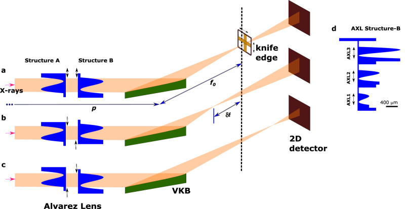
Visible light optical elements such as lenses and mirrors have counterparts for X-rays. In the visible regime, a variable focusing power can be achieved by an Alvarez lens which consists of a pair of inline planar refractors with a cubic thickness profile. When the two refractors are laterally displaced in opposite directions, the parabolic component of the wavefront is changed resulting in a longitudinal displacement of the focus. This paper reports an implementation of this concept for X-rays using two planar microfabricated refractive elements. The Alvarez X-ray lens can vary the focal distance of an elliptical X-ray mirror or a planar compound X-ray lens over several millimetres. The study presents the first demonstration of an Alvarez X-ray lens which adaptively corrects defocus and astigmatism aberrations of X-ray optics. In addition, the Alvarez X-ray lens eliminates coma aberration in an elliptical mirror, to the lowest order, when combining the lens with an adjustment of the pitch angle of the mirror.
© 2023. Crown.
Conflict of interest statement
The authors declare no competing interests.
Figures


Similar articles
-
Cubic optical elements for an accommodative intraocular lens.Opt Express. 2006 Aug 21;14(17):7757-75. doi: 10.1364/oe.14.007757. Opt Express. 2006. PMID: 19529146
-
MEMS-actuated metasurface Alvarez lens.Microsyst Nanoeng. 2020 Oct 5;6:79. doi: 10.1038/s41378-020-00190-6. eCollection 2020. Microsyst Nanoeng. 2020. PMID: 34567689 Free PMC article.
-
Optical characteristics of Alvarez variable-power spectacles.Ophthalmic Physiol Opt. 2017 May;37(3):284-296. doi: 10.1111/opo.12361. Epub 2017 Feb 17. Ophthalmic Physiol Opt. 2017. PMID: 28211160
-
[Quantitative assessment of quality of vision].Nippon Ganka Gakkai Zasshi. 2004 Dec;108(12):770-807; discussion 808. Nippon Ganka Gakkai Zasshi. 2004. PMID: 15656087 Review. Japanese.
-
MEMS Varifocal Optical Elements for Focus Control.Micromachines (Basel). 2025 Apr 19;16(4):482. doi: 10.3390/mi16040482. Micromachines (Basel). 2025. PMID: 40283357 Free PMC article. Review.
Cited by
-
Research on the Polishing Process of Wolter-I Type Grazing Incidence Mirrors.PLoS One. 2025 Mar 13;20(3):e0317239. doi: 10.1371/journal.pone.0317239. eCollection 2025. PLoS One. 2025. PMID: 40080511 Free PMC article.
-
Ultrathin monolithic bimorph mirror using polarization-inverted lithium niobate wafer.Sci Rep. 2025 Jun 27;15(1):20238. doi: 10.1038/s41598-025-05019-8. Sci Rep. 2025. PMID: 40579419 Free PMC article.
-
Wavefront analysis and phase correctors design using SHADOW.J Synchrotron Radiat. 2024 May 1;31(Pt 3):438-446. doi: 10.1107/S1600577524002728. Epub 2024 Apr 23. J Synchrotron Radiat. 2024. PMID: 38652579 Free PMC article.
References
-
- Mino L, et al. Materials characterization by synchrotron x-ray microprobes and nanoprobes. Rev. Mod. Phys. 2018;90:025007. doi: 10.1103/RevModPhys.90.025007. - DOI
-
- Cocco D, et al. Wavefront preserving X-ray optics for Synchrotron and Free Electron Laser photon beam transport systems. Phys. Rep. 2022;974:1–40. doi: 10.1016/j.physrep.2022.05.001. - DOI
Grants and funding
LinkOut - more resources
Full Text Sources
