. 2023 Oct;12(25):e2300528.
doi: 10.1002/adhm.202300528. Epub 2023 Aug 17.

Tumor Shape-Specific Brachytherapy Implants by 3D-Printing, Precision Radioactivity Painting, and Biomedical Imaging

Affiliations

Tumor Shape-Specific Brachytherapy Implants by 3D-Printing, Precision Radioactivity Painting, and Biomedical Imaging

Théophraste Lescot et al. Adv Healthc Mater. 2023 Oct.

Abstract

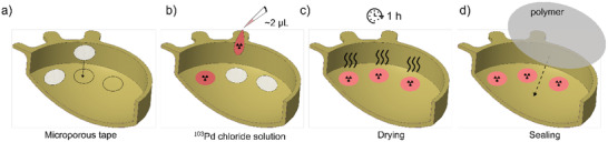
In brachytherapy (BT), or internal radiation therapy, cancer is treated by radioactive implants. For instance, episcleral plaques (EPs) for the treatment of uveal melanoma, are designed according to generic population approximations. However, more personalized implants can enhance treatment precision through better adjustment of dose profiles to the contours of cancerous tissues. An original approach integrating biomedical imaging, 3D printing, radioactivity painting, and biomedical imaging, is developed as a workflow for the development of tumor shape-specific BT implants. First, computer-aided design plans of EP are prepared according to guidelines prescribed by the Collaborative Ocular Melanoma Study protocol. Polyetheretherketone (PEEK), a high-performance polymer suitable for permanent implants, is used to 3D-print plaques and the geometrical accuracy of the printed design is evaluated by imaging. The possibility to modulate the dose distribution in a tridimensional manner is demonstrated by painting the inner surfaces of the EPs with radioactive 103Pd, followed by dose profile measurements. The possibility to modulate dose distributions generated by these 3D-printed plaques through radioactivity painting is therefore confirmed. Ex vivo surgical tests on human eyeballs are performed as an assessment of manipulation ease. Overall, this work provides a solution for the fabrication of tumor-specific radioactive implants requiring higher dose precision.

Keywords: 3D printing metrology; additive manufacturing of polymers; brachytherapy; brachytherapy dosimetry; episcleral plaques; polyetheretherketone (PEEK); uveal melanoma.


Conflict of interest statement

The authors declare no conflict of interest.

Figures

Figure 1
Figure 1
a) Picture of a conventional COMS plaque (in metal), taken from the inside, with the radioactive seeds visible under the silastic layer; b,c) schematic representations of the standard radioactive seeds positioning with respect to the plaque; d) schematic representation of plaque surgical fixation on the sclera; e) dimensions of a typical COMS plaque (18 mm diameter) and illustration of the geometry of a tumor to be irradiated with the radioactive load (typical 85 Gy prescription dose at the apex); f) cross‐section and dimensions of a 14 mm diameter EP extracted from the COMS protocol, and exploited in the design of .stl files for polymer 3D printing in the present study (dimensions and schematic representations are adapted from ref. [20b]).
Figure 2
Figure 2
a) Schematic representation of the printing layout for a series of replicates of 14 mm diameter EPs. Image generated from the slicer software. b) High‐quality hemisphere‐shaped 3D‐printed PEEK plaques (10, 14, or 22 mm diameter EPs), at the post‐printing processing step.
Figure 3
Figure 3
Steps of the design, printing process, and geometrical accuracy evaluation of the EPs produced by PEEK 3D printing: 1) Drawing of a 3D CAD model conforms to the COMS protocol; 2) adaptation of the 3D model to suit the requirements of FFF AM; 3) slicing process to generate .gcode files (gray = supports; purple = brim; green = infill; blue = perimeter (outskirts); 4) 3D printing of plaques; 5) post‐processing; 6) CT scanning; 7) 3D image segmentation; 8) comparative geometrical analysis (CT scans vs CAD files).
Figure 4
Figure 4
3D geometrical deviation maps for a) 10, c) 14, and e) 22 mm diameter plaques. Warm colors represent the areas associated with the strongest deviations from the original CAD numeric prints. Corresponding histograms (b, d, f) are also represented, suggesting different populations of “deviations.”
Figure 5
Figure 5
3D geometrical deviation maps dissected between a) the ring and lugs region, and b) the cupola region, for a,b) 10, c,d) 14, and e,f) 22 mm diameter plaques. Warm colors represent the areas associated with the strongest deviations from the original CAD numeric prints. Corresponding histograms are also represented, revealing the different populations of geometrical “deviations.”
Figure 6
Figure 6
Radial cross‐sections of each plaque model: close‐up on the intersection between the cupola, the ring, and the suture lug parts. The black line represents the initial CAD drawing contours, whereas the superposed shaded areas represent the corresponding cross‐sections of the 3D‐printed volumes after printing, imaging, and numeric comparison.
Figure 7
Figure 7
Dose patterns radioactivity painting: a) four patterns of radioactivity prints encapsulated in the polymer liner of the plaques. b) Schematic representation of the experimental setup used to perform the dose distribution study.
Figure 8
Figure 8
Dose distribution after radiation exposure of the first four dosimetric films stacked on EPs corresponding to cases a) 1, b) 2, d) 3, and e) 4 (from left to right); 0 corresponds to the minimum intensity and 1 corresponds to the maximum intensity. Isodoses corresponding to 25% (pink), 60% (yellow), and 90% (red) are added to allow a better visualization of the dose profile shape. For each one of the four cases, cross‐sections of the dose distributions are provided (c, f) which were taken from the axes represented by the dashed lines on the dosimetric films.
Figure 9
Figure 9
Manipulation of 3D‐printed polymer EPs: surgical tests on human donor eyeballs: a) 14 mm diameter 3D‐printed plaques; b) surgical instruments used: 1) sterile gauze, 2) eyeball support, 3) suture film, 4) sterile irrigation solution, and 5) tweezers; c) plaque positioning at the surface of the eyeball; d) position marking of the suture lugs on the sclera; e) sewing of intrascleral suturing points; f) cutting excess threads after knotting.
Figure 10
Figure 10
Schematic representation of the radioactivity painting procedure inside of the 3D‐printed plaques. First, a) coupons of adhesive microporous tape are placed on the plaque; b) radioactive drops are placed on the microporous liners, and left to dry for 1 h; c,d) finally, a hermetic polymer membrane is applied to seal the radioactive pattern.

Similar articles

Cited by

References

    1. a) Pei X., Zhang B., Fan Y., Zhu X., Sun Y., Wang Q., Zhang X., Zhou C., Mater. Lett. 2017, 208, 133;
    2. b) de Moraes P. H., Olate S., Cantín M., Assis A. F., Santos E., Silva F. d. O., Silva L. d. O., Int. J. Morphol. 2015, 33, 826;
    3. c) Murr L. E., Gaytan S. M., Medina F., Lopez H., Martinez E., Machado B. I., Hernandez D. H., Martinez L., Lopez M. I., Wicker R. B., Bracke J., Philos. Trans. R. Soc., A 2010, 368, 1999; - PubMed
    4. d) Ryan G., Pandit A., Apatsidis D. P., Biomaterials 2006, 27, 2651. - PubMed
    1. a) Bhargav A., Sanjairaj V., Rosa V., Feng L. W., Fuh Yh J., J. Biomed. Mater. Res., Part B 2018, 106, 2058; - PubMed
    2. b) Bibb R., Eggbeer D., Williams R., Rapid Prototyping J. 2006, 12, 95.
    1. a) Leong K. F., Cheah C. M., Chua C. K., Biomaterials 2003, 24, 2363; - PubMed
    2. b) Leong K. F., Chua C. K., Sudarmadji N., Yeong W. Y., J. Mech. Behav. Biomed. Mater. 2008, 1, 140; - PubMed
    3. c) Melchels F. P. W., Bertoldi K., Gabbrielli R., Velders A., Feijen J., Grijpma D. W., Biomaterials 2010, 31, 6909; - PubMed
    4. d) Zein I., Hutmacher D. W., Tan K. C., Teoh S. H., Biomaterials 2002, 23, 1169; - PubMed
    5. e) Shi J., Zhu L., Li L., Li Z., Yang J., Wang X., Sci. Rep. 2018, 8, 7395; - PMC - PubMed
    6. f) Tino R. B., Leary M., Yeo A. U., Kyriakou E., Kron T., Brandt M., Int. J. Extreme Manuf. 2020, 2, 012003;
    7. g) Poomathi N., Singh S., Prakash C., Subramanian A., Sahay R., Cinappan A., Ramakrishna S., Rapid Prototyping J. 2020, 26, 1313;
    8. h) Bose S., Ke D., Sahasrabudhe H., Bandyopadhyay A., Prog. Mater. Sci. 2018, 93, 45; - PMC - PubMed
    9. i) Li J. H., Wu C. T., Chu P. K., Gelinsky M., Mater. Sci. Eng., R 2020, 140, 100543;
    10. j) Vijayavenkataraman S., Yan W. C., Lu W. F., Wang C. H., Fuh J. Y. H., Adv. Drug Delivery Rev. 2018, 132, 296. - PubMed
    1. a) Song W. Y., Tanderup K., Pieters B., Emerging Technologies in Brachytherapy, CRC Press, Taylor & Francis Group, Boca Raton, FL: 2017;
    2. b) Tino R., Leary M., Yeo A., Kyriakou E., Kron T., Brandt M., Int. J. Extreme Manuf. 2020, 2, 012003.
    1. Honigmann P., Sharma N., Okolo B., Popp U., Msallem B., Thieringer F. M., Biomed Res. Int. 2018, 2018, 4520636. - PMC - PubMed

Publication types

Grants and funding

LinkOut - more resources