. 2023 Aug 3;13(1):12628.
doi: 10.1038/s41598-023-39468-w.

A porcine model of postoperative hemi-diaphragmatic paresis to evaluate a unilateral diaphragmatic pacemaker

Affiliations

A porcine model of postoperative hemi-diaphragmatic paresis to evaluate a unilateral diaphragmatic pacemaker

Tobias Kratz et al. Sci Rep. .

Abstract

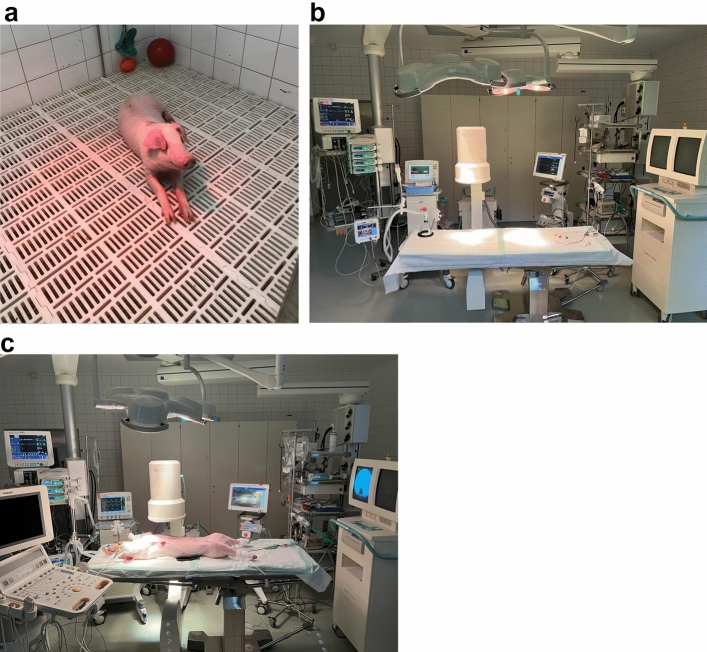
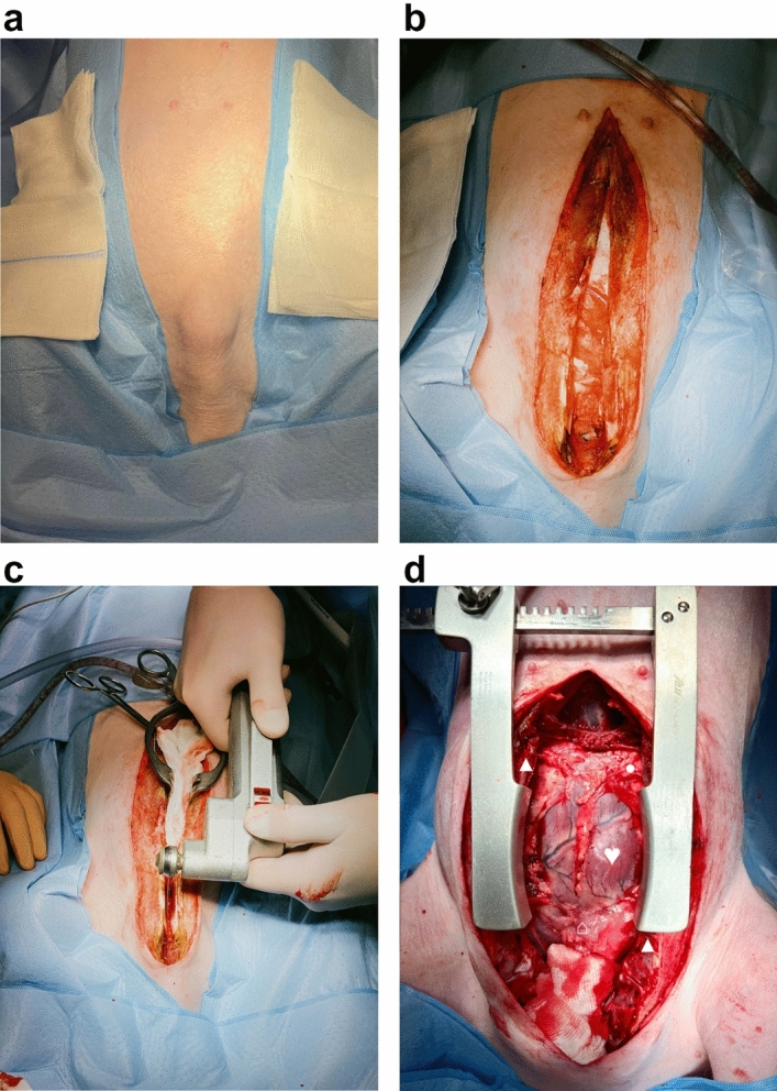
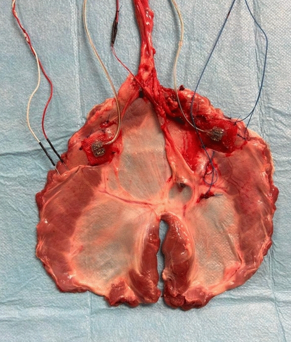
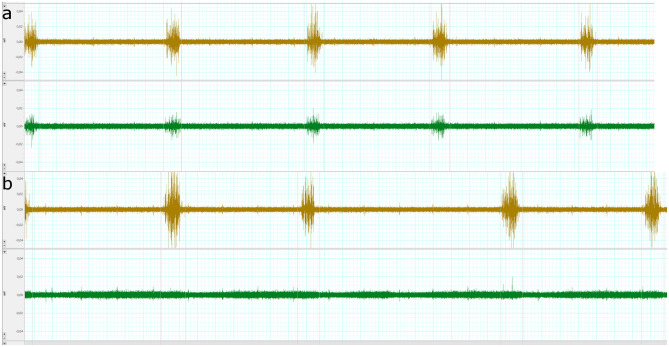
Unilateral phrenic nerve damage is a dreaded complication in congenital heart surgery. It has deleterious effects in neonates and children with uni-ventricular circulation. Diaphragmatic palsy, caused by phrenic nerve damage, impairs respiratory function, especially in new-borns, because their respiration depends on diaphragmatic contractions. Furthermore, Fontan patients with passive pulmonary perfusion are seriously affected by phrenic nerve injury, because diaphragmatic contraction augments pulmonary blood flow. Diaphragmatic plication is currently employed to ameliorate the negative effects of diaphragmatic palsy on pulmonary perfusion and respiratory mechanics. This procedure attenuates pulmonary compression by the abdominal contents. However, there is no contraction of the plicated diaphragm and consequently no contribution to the pulmonary blood flow. Hence, we developed a porcine model of unilateral diaphragmatic palsy in order to evaluate a diaphragmatic pacemaker. Our illustrated step-by-step description of the model generation enables others to replicate and use our model for future studies. Thereby, it might contribute to investigation and advancement of potential improvements for these patients.


Conflict of interest statement

The authors declare no competing interests.

Figures

Figure 1
Figure 1
Swine and the experimental setup. (a) A representative swine in its box laying partially under the heat lamp with some of the material to play with in the background. (b) Our operation room with its full setup without the swine and without the echo. (c) The full setup for our experiment before preparation and application of the surgical drapes to the pig.
Figure 2
Figure 2
Getting access to the heart. The orientation is the same in all pictures: the rostral direction is at the bottom and the caudal direction at the top of the picture. (a) Pre-operative situation after full draping of the swine. (b) Skin incision via blade and monopolar preparation of the subcutaneous tissues until the sternum was exposed. (c) Median sternotomy using an oscillating bone saw. (d) Full exposure of the heart from its base to the apex and bilateral access to both hemi-diaphragms. ♥ designates the heart.▲ designates the sternum. ● designate the pericardium. ⌂ designates the thymus.
Figure 3
Figure 3
Instrumentation of the left hemi-diaphragm. The orientation is the same in all pictures: the rostral direction is at the bottom and the caudal direction at the top of the picture. ♥ designates the heart.▲ designates the sternum. ● designate the pericardium. ■ designates the diaphragm. ♦ designates the lung. ⌂ designates the thymus. (a) Detailed depiction of the accelerometer used in the experiment. (b) Positioning of the accelerometer to the most cranial point of the swine’s left hemi-diaphragm. (c) Fixation of the accelerometer to the diaphragm via four simple stitches to the edges of the accelerometer. (d) Detailed depiction of the hook electrodes used for electromyogram readings. (e) Implantation of the hook electrodes to the left hemi-diaphragm. (f) Positioning of the hook electrodes as lateral as possible and close to the chest wall with 10 mm distance between its poles.
Figure 4
Figure 4
Instrumentation of the right hemi-diaphragm. The orientation is the same in all pictures: the rostral direction is at the bottom and the caudal direction at the top of the picture, except for panel (a), in which caudal is top right and rostral bottom left of the picture. ♥ designates the heart.▲ designates the sternum. ● designate the pericardium. ■ designates the diaphragm. ♦ designates the lung. ⌂ designates the thymus. (a) Fixation of the cables to the skin directly adjacent to the sternotomy wound with simple stitches. (b) Implantation of an accelerometer to the most cranial point of the right hemi-diaphragm. (c) Fixation of the accelerometer to the right hemi-diaphragm via simple stitches to the edges of the accelerometer. (d) Detailed depiction of the hook electrodes used for diaphragmatic pacing. (e) Implantation of the pacing electrodes directly adjacent to the insertion of the phrenic nerve into the diaphragm. (f) Fixation of the cables of the implanted devices to the skin. Note the distance of approximately 10 mm between the poles of the pacing electrodes.
Figure 5
Figure 5
Instrumentation of the right phrenic nerve. The orientation is different to the preceding figures: In panels (a) and (b), the rostral direction is at the top left and caudal direction is at the bottom right of the picture. In panels (d) and (e), the rostral direction is at the top and the caudal direction at the bottom of the picture. In panels (c) and (f), the rostral direction is at the bottom and the caudal direction at the top of the picture. ♥ designates the heart.▲ designates the sternum. ● designate the pericardium. ■ designates the diaphragm. ♦ designates the lung. ← designates the phrenic nerve. → designates the vagus nerve. ▌ designates the oesophagus. ∫ designates the vena cava inferior. ∞ designates the azygos vein. ⌂ designates the thymus. (a) Detailed depiction of the silicone-cuff-electrode for bipolar neurostimulation for the phrenic nerve. (b) The right pleura was opened and the phrenic nerve identified along its course. (c) The intended position of the neurostimulation electrode along the phrenic nerve at the level of the inferior vena cava. (d) Increased exposure of the right phrenic nerve after a limited sharp neurolysis to allow placement of the neurostimulator electrode. (e) Final setup with all devices implanted. (f) Detailed depiction of the neurostimulator electrode at the phrenic nerve.
Figure 6
Figure 6
Topview depiction of the experimental setup with all implanted devices affixed to it. The orientation of the specimen corresponds to the viewpoint.
Figure 7
Figure 7
Electromyography readings confirmed unilateral diaphragmatic hemiparesis and success of the external stimulation. The upper curve in both panels represents the left hemi-diaphragm and the lower curve in both panels represents the right hemi-diaphragm. A 100 Hz high pass filter was used. (a) The phrenic nerves of both hemi-diaphragms work in parallel and both hemi-diaphragms show muscle activity in parallel as depicted by the electromyography readings. (b) Following transection of the right phrenic nerve, the electromyogram of the right hemi-diaphragm does not show any muscle activity, whereas the left hemi-diaphragm shows the same activity as before.
Figure 8
Figure 8
Ultrasound examination of the externally stimulated right phrenic nerve. (a) Minimal diaphragmatic excursion without stimulation during the inspiratory cycle of the respirator. (b) Regular diaphragmatic excursion following external stimulation of the nerve with a stimulus of 0.5 mA.
Figure 9
Figure 9
Histologic analyses revealed no damage to the diaphragm. All panels represent a 10-times magnification. Panels (ac) represent a cross-sectional view of the paced diaphragm. Panels (df) represent a longitudinal view of the paced diaphragm. Panels (gi) represent the cross-sectional view of a healthy diaphragm and shows no difference compared to the paced diaphragm. In panels (a), (d), (g) Hematoxylin–eosin staining was used, in panels (b), (e), (h) Elastica-van Gieson staining was used, and in panels (c), (f), (i) Masson’s trichrome stain was used.

References

    1. Mickell JJ, et al. Clinical implications of postoperative unilateral phrenic nerve paralysis. J. Thorac. Cardiovasc. Surg. 1978;76:297–304. doi: 10.1016/S0022-5223(19)39570-4. - DOI - PubMed
    1. Fraser CD, et al. Diaphragm paralysis after pediatric cardiac surgery: An STS congenital heart surgery database study. Ann. Thorac. Surg. 2021;112:139–146. doi: 10.1016/j.athoracsur.2020.05.175. - DOI - PubMed
    1. Denamur S, et al. Outcome analysis of a conservative approach to diaphragmatic paralysis following congenital cardiac surgery in neonates and infants: A bicentric retrospective study. Interact. Cardiovasc. Thorac. Surg. 2021;33:597–604. doi: 10.1093/icvts/ivab123. - DOI - PMC - PubMed
    1. Baker CJ, et al. Hemidiaphragm plication after repair of congenital heart defects in children: Quantitative return of diaphragm function over time. J. Thorac. Cardiovasc. Surg. 2008;135:56–61. doi: 10.1016/j.jtcvs.2007.09.031. - DOI - PubMed
    1. Smith BM, Ezeokoli NJ, Kipps AK, Azakie A, Meadows JJ. Course, predictors of diaphragm recovery after phrenic nerve injury during pediatric cardiac surgery. Ann. Thorac. Surg. 2013;96:938–942. doi: 10.1016/j.athoracsur.2013.05.057. - DOI - PubMed

Publication types