. 2023 Jul 18;11(30):11019-11031.
doi: 10.1021/acssuschemeng.3c00760. eCollection 2023 Jul 31.

Nature-Inspired Surface Engineering for Efficient Atmospheric Water Harvesting

Affiliations

Nature-Inspired Surface Engineering for Efficient Atmospheric Water Harvesting

Zihao Li et al. ACS Sustain Chem Eng. .

Abstract

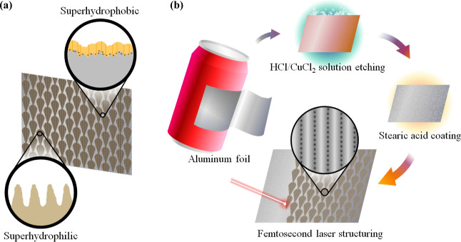
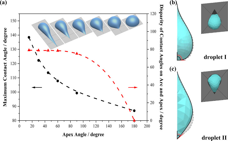
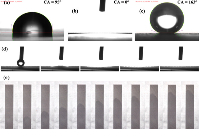
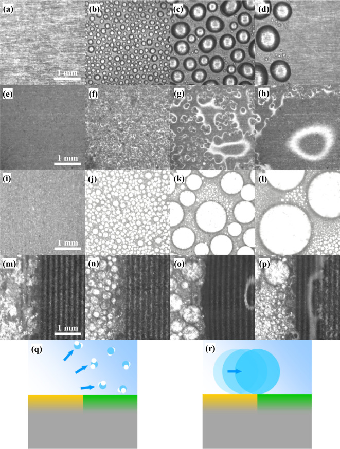
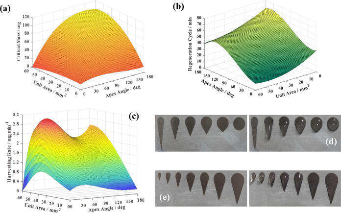
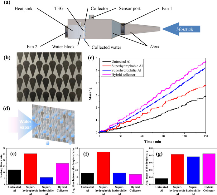
Atmospheric water harvesting is a sustainable solution to global water shortage, which requires high efficiency, high durability, low cost, and environmentally friendly water collectors. In this paper, we report a novel water collector design based on a nature-inspired hybrid superhydrophilic/superhydrophobic aluminum surface. The surface is fabricated by combining laser and chemical treatments. We achieve a 163° contrast in contact angles between the superhydrophilic pattern and the superhydrophobic background. Such a unique superhydrophilic/superhydrophobic combination presents a self-pumped mechanism, providing the hybrid collector with highly efficient water harvesting performance. Based on simulations and experimental measurements, the water harvesting rate of the repeating units of the pattern was optimized, and the corresponding hybrid collector achieves a water harvesting rate of 0.85 kg m-2 h-1. Additionally, our hybrid collector also exhibits good stability, flexibility, as well as thermal conductivity and hence shows great potential for practical application.


Conflict of interest statement

The authors declare no competing financial interest.

Figures

Figure 1
Figure 1
(a) Schematic diagram of the hybrid collector, including zoom-in cross-sectional views of the superhydrophobic background (top) and the superhydrophilic pattern (bottom). (b) Schematic illustration of the fabrication sequence: (1) Al foil being cut into pieces as raw material. (2) Etching of the Al foil to obtain a surface with microroughness. (3) Stearic acid-coating of the etched Al to form a superhydrophobic background. (4) Selective fs-laser-ablation to create a superhydrophilic pattern (zoom-in is the top view of the microchannels and self-organized microhole array introduced by fs-laser).
Figure 2
Figure 2
Simulations of the shape of water droplets. (a) Superhydrophilic units with the same area of 10 mm2 but different apex angles of 15, 30, 45, 60, 90, and 180° and the maximum contact angle of a water droplet with the mass of 20 mg that is constrained inside the corresponding unit. Apex angle versus maximum contact angle: disparity of contact angles on the arc and apex side of the unit of each droplet are shown in black and red with fitted curves (dashed lines). Side view of water droplets with mass of 50 mg constrained inside units with the shape of (b) erected teardrop and (c) inverted teardrop with fixed apex angle of 60° and area of 50 mm2 on a vertically placed collector with and without vertical disturbance (shown in blue and gray, respectively).
Figure 3
Figure 3
(a) 3D CLSM map and corresponding (b) SEM image of the superhydrophobic region of the hybrid collector. (c) CLSM map and corresponding (d) SEM image of the superhydrophilic region of the hybrid collector. Different colors in the elevation maps from blue to red only represent the relative elevation from low to high. (e) Effects of the fs-laser scan numbers on the diameters and depths of the microholes along with the volume of the condensed water in a microhole at equilibrium state.
Figure 4
Figure 4
Contact angles of a water droplet on (a) untreated, (b) chemically-etched, and (c) stearic acid-coated Al samples. (d) Frames taken from a high-speed camera video of a water droplet at 0, 5, 10, 50, and 100 ms (from left to right) after it touched the surface of a horizontally placed fs-laser-treated Al sample. (e) Time-series snapshots of positions of the waterfront on a vertically mounted fs-laser-ablated Al foil with its microchannels parallel to the direction of gravitational force and its lower end brought in contact with the water surface. The time interval between two neighboring frames is 0.25 s (from left to right). The line spacing and the scan number are 0.15 and 5, respectively. The red dashed lines are indication of the waterfront.
Figure 5
Figure 5
Microphotos recorded during the water condensation and regeneration process on (a–d) untreated, (e–h) completely superhydrophilic, (i–l) completely superhydrophobic, and (m–p) hybrid superhydrophilic/superhydrophobic Al. Schematic illustration of the two major water harvesting mechanisms of the hydrophobic/hydrophilic hybrid water collector take place in (q) gas phase and (r) liquid phase shown in cross section. Hydrophobic and hydrophilic regions of the collector are shown in yellow and green, respectively.
Figure 6
Figure 6
Dependency of (a) critical mass of water that can be constrained within one repeating unit of the pattern, (b) length of a regeneration cycle, and (c) water harvesting rate of one superhydrophilic unit on the area and the apex angle of the repeating unit. Photo showing before (left) and after (right) putting the same amount of water onto the teardrop-shaped superhydrophilic units with (d) apex angles of 15, 30, 45, 60, 90, and 180° and a constant area of 45 mm2, and (e) area of 3.14, 7.07, 12.57, 19.63, 28.27, 38.48, and 50.27 mm2 and a constant apex angle of 35°.
Figure 7
Figure 7
(a) Schematic setup for measuring water harvesting performances of different collectors. (b) Photo of a hybrid collector. (c) Water harvesting rates of untreated Al, complete superhydrophilic Al, complete superhydrophobic Al, and the hybrid collector. (d) Schematic illustration of the water harvesting process of the hybrid collector. (e) Start-up time, (f) average time interval between two successive droplets, and (g) average mass of the collected droplets of different collectors.

References

    1. Oki T.; Kanae S. Global hydrological cycles and world water resources. science 2006, 313, 1068–1072. 10.1126/science.1128845. - DOI - PubMed
    2. Boretti A.; Rosa L. Reassessing the projections of the world water development report. npj Clean Water 2019, 2, 15. 10.1038/s41545-019-0039-9. - DOI
    1. Fessehaye M.; Abdul-Wahab S. A.; Savage M. J.; Kohler T.; Gherezghiher T.; Hurni H. Fog-water collection for community use. Renewable Sustainable Energy Rev. 2014, 29, 52–62. 10.1016/j.rser.2013.08.063. - DOI
    1. Wuebbles D. J.; Grant K. E.; Connell P. S.; Penner J. E. The role of atmospheric chemistry in climate change. Japca 1989, 39, 22–28. 10.1080/08940630.1989.10466502. - DOI
    1. Schemenauer R. S.; Cereceda P. A proposed standard fog collector for use in high-elevation regions. J. Appl. Meteorol. Climatol. 1994, 33, 1313–1322. 10.1175/1520-0450(1994)033<1313:apsfcf>2.0.co;2. - DOI
    1. Bormashenko E.; Fedorets A. A.; Frenkel M.; Dombrovsky L. A.; Nosonovsky M. Clustering and self-organization in small-scale natural and artificial systems. Philos. Trans. R. Soc., A 2020, 378, 20190443. 10.1098/rsta.2019.0443. - DOI - PMC - PubMed