

Modelling and robust controller design for an underactuated self-balancing robot with uncertain parameter estimation
- PMID: 37556480
- PMCID: PMC10411822
- DOI: 10.1371/journal.pone.0285495
Modelling and robust controller design for an underactuated self-balancing robot with uncertain parameter estimation
Abstract
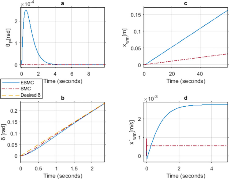
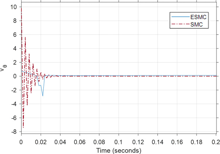
A comprehensive literature review of self-balancing robot (SBR) provides an insight to the strengths and limitations of the available control techniques for different applications. Most of the researchers have not included the payload and its variations in their investigations. To address this problem comprehensively, it was realized that a rigorous mathematical model of the SBR will help to design an effective control for the targeted system. A robust control for a two-wheeled SBR with unknown payload parameters is considered in these investigations. Although, its mechanical design has the advantage of additional maneuverability, however, the robot's stability is affected by changes in the rider's mass and height, which affect the robot's center of gravity (COG). Conventionally, variations in these parameters impact the performance of the controller that are designed with the assumption to operate under nominal values of the rider's mass and height. The proposed solution includes an extended Kalman filter (EKF) based sliding mode controller (SMC) with an extensive mathematical model describing the dynamics of the robot itself and the payload. The rider's mass and height are estimated using EKF and this information is used to improve the control of SBR. Significance of the proposed method is demonstrated by comparing simulation results with the conventional SMC under different scenarios as well as with other techniques in literature. The proposed method shows zero steady state error and no overshoot. Performance of the conventional SMC is improved with controller parameter estimation. Moreover, the stability issue in the reaching phase of the controller is also solved with the availability of parameter estimates. The proposed method is suitable for a wide range of indoor applications with no disturbance. This investigation provides a comprehensive comparison of available techniques to contextualize the proposed method within the scope of self-balancing robots for indoor applications.
Copyright: © 2023 Choudhry et al. This is an open access article distributed under the terms of the Creative Commons Attribution License, which permits unrestricted use, distribution, and reproduction in any medium, provided the original author and source are credited.
Conflict of interest statement
The authors have declared that no competing interests exist.
Figures


References
-
- Boubaker O., "The inverted pendulum benchmark in nonlinear control theory: a survey," International Journal of Advanced Robotic Systems, vol. 10, no. 5, p. 233, 2013.
-
- Irfan S., Mehmood A., Razzaq M. T., and Iqbal J., "Advanced sliding mode control techniques for Inverted Pendulum: Modelling and simulation," Engineering science and technology, an international journal, vol. 21, no. 4, pp. 753–759, 2018.
-
- Kafetzis I. and Moysis L., "Inverted Pendulum: A system with innumerable applications," School of Mathematical Sciences, 2017.
-
- Hasan M., Saha C., Rahman M. M., Sarker M. R. I., and Aditya S. K., "Balancing of an inverted pendulum using PD controller," Dhaka University Journal of Science, vol. 60, no. 1, pp. 115–120, 2012.
-
- Khan H., Iqbal J., Baizid K., and Zielinska T., "Longitudinal and lateral slip control of autonomous wheeled mobile robot for trajectory tracking," Frontiers of Information Technology & Electronic Engineering, vol. 16, pp. 166–172, 2015.
Publication types
MeSH terms
LinkOut - more resources
Full Text Sources
