. 2023 Aug 9;18(8):e0288529.
doi: 10.1371/journal.pone.0288529. eCollection 2023.

10-channel phased-array coil for carotid wall MRI at 3T

Affiliations

10-channel phased-array coil for carotid wall MRI at 3T

Matthijs H S de Buck et al. PLoS One. .

Abstract

Background: Accurate assessment of plaque accumulation near the carotid bifurcation is important for the effective prevention and treatment of stroke. However, vessel and plaque delineation using MRI can be limited by low contrast-to-noise ratio (CNR) and long acquisition times. In this work, a 10-channel phased-array receive coil design for bilateral imaging of the carotid bifurcation using 3T MRI is proposed.

Methods: The proposed 10-channel receive coil was compared to a commercial 4-channel receive coil configuration using data acquired from phantoms and healthy volunteers (N = 9). The relative performance of the coils was assessed, by comparing signal-to-noise ratio (SNR), noise correlation, g-factor noise amplification, and the CNR between vessel wall and lumen using black-blood sequences. Patient data were acquired from 12 atherosclerotic carotid artery disease patients.

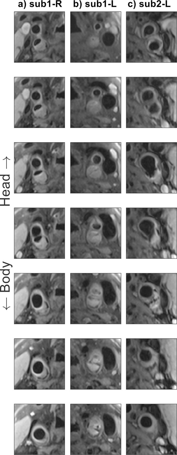
Results: The 10-channel coil consistently provided substantially increased SNR in phantoms (+77 ± 27%) and improved CNR in healthy carotid arteries (+62 ± 11%), or reduced g-factor noise amplification. Patient data showed excellent delineation of atherosclerotic plaque along the length of the carotid bifurcation using the 10-channel coil.

Conclusions: The proposed 10-channel coil design allows for improved visualization of the carotid arteries and the carotid bifurcation and increased parallel imaging acceleration factors relative to a commercial 4-channel coil design.


Conflict of interest statement

I have read the journal’s policy and the authors of this manuscript have the following competing interests: MdB receives studentship support from Siemens Healthineers and CR is an employee of PulseTeq Limited. We confirm that our competing interests do not alter our adherence to PLOS ONE policies on sharing data and materials, and have included this in the cover letter as requested.

Figures

Fig 1
Fig 1. The two coils used in this work.
(a): The 4-channel coil positioned around the neck of a volunteer. (b): The 10-channel coil positioned around the neck of a (different) volunteer. The green arrows indicate the degrees of freedom of the coil positioning around the neck of the subject. (c-d) Relative positions and dimensions of 4-channel [20] and 10-channel coils and their individual channels (figures show one of the bilateral sides).
Fig 2
Fig 2
SNR-units reconstructions from transverse T1-weighted turbo-spin-echo data for one healthy volunteer SNR, acquired without parallel imaging acceleration using (a) the 4-channel coil and (b) the 10-channel coil. SNR contours are shown for both acquisitions at iso-contour levels of 10, 20, 30, and 40.
Fig 3
Fig 3
Noise correlation matrices for (a) the 4-channel coil and (b) the 10-channel coil. The unilateral coil elements correspond to indices 1–2 and 3–4 for the 4-channel coil and indices 1–5 and 6–10 for the 10-channel coil.
Fig 4
Fig 4
Estimated g-factor noise amplification in a phantom using the 4-channel and the 10-channel coils, at (a) R = 2 and (b) R = 3. Reconstructions as well as retained SNR (inverse g-factor) maps of a single coronal slice are shown for both coils and at both acceleration factors. The bottom row shows the maximum g-factor in each slice for both the transverse and coronal acquisitions. Note that the maximum g-factor values are shown using a different y-axis scaling in Fig (a) than in Fig (b).
Fig 5
Fig 5
In vivo estimated g-factor noise amplification using the 4-channel and the 10-channel coils, at (a) R = 2 and (b) R = 3. All data is shown for transverse acquisitions. The top two rows show reconstructions as well as retained SNR (inverse g-factor) maps of a single transverse slice for both coils and at both acceleration factors. The bottom row shows the maximum transverse g-factor in each slice. Note that the maximum g-factor values are shown using a different y-axis scaling in Fig (a) than in Fig (b).
Fig 6
Fig 6. DANTE-MESE scans of nine healthy volunteers using both coils.
All data is shown to the same greyscale. (a-b) Close-ups near the carotid bifurcation of a single volunteer at four different echo times using (a) the 4-channel coil and (b) the 10-channel coil. (c) Mean carotid wall/lumen CNR results of both coils across the nine volunteers.
Fig 7
Fig 7. Consecutive DANTE-FSE T1-weighted slice segments showing the carotid bifurcations in two patients with atherosclerotic carotid artery disease, acquired using the new 10-channel coil.
(a-b) Subject 1, left- and right-hand sides; (c) subject 2, right-hand side.

References

    1. Masaryk TJ, Ross JS, Modic MT, Lenz GW, Haacke EM. Carotid Bifurcation: MR Imaging. Neuroradiology. 1988;166: 461–466. - PubMed
    1. Redgrave JN, Gallagher P, Lovett JK, Rothwell PM. Critical cap thickness and rupture in symptomatic carotid plaques: The oxford plaque study. Stroke. 2008;39: 1722–1729. doi: 10.1161/STROKEAHA.107.507988 - DOI - PubMed
    1. Balu N, Chu B, Hatsukami TS, Yuan C, Yarnykh VL. Comparison between 2D and 3D high-resolution black-blood techniques for carotid artery wall imaging in clinically significant atherosclerosis. Journal of Magnetic Resonance Imaging. 2008;27: 918–924. doi: 10.1002/jmri.21282 - DOI - PMC - PubMed
    1. Van Lammeren GW, Reichmann BL, Moll FL, Bots ML, De Kleijn DPV, De Vries JPPM, et al.. Atherosclerotic plaque vulnerability as an explanation for the increased risk of stroke in elderly undergoing carotid artery stenting. Stroke. 2011;42: 2550–2555. doi: 10.1161/STROKEAHA.110.607382 - DOI - PubMed
    1. Lindsay AC, Biasiolli L, Knight S, Cunnington C, Robson MD, Neubauer S, et al.. Non-invasive imaging of carotid arterial restenosis using 3T cardiovascular magnetic resonance. Journal of Cardiovascular Magnetic Resonance. 2014;16: 1–8. doi: 10.1186/1532-429X-16-5 - DOI - PMC - PubMed

Publication types

MeSH terms