Review
. 2023 Jul 29;15(15):3235.
doi: 10.3390/polym15153235.

Advances in Graphene-Polymer Nanocomposite Foams for Electromagnetic Interference Shielding

Affiliations
Review

Advances in Graphene-Polymer Nanocomposite Foams for Electromagnetic Interference Shielding

Jiaotong Sun et al. Polymers (Basel). .

Abstract

With the continuous advancement of wireless communication technology, the use of electromagnetic radiation has led to issues such as electromagnetic interference and pollution. To address the problem of electromagnetic radiation, there is a growing need for high-performance electromagnetic shielding materials. Graphene, a unique carbon nanomaterial with a two-dimensional structure and exceptional electrical and mechanical properties, offers advantages such as flexibility, light weight, good chemical stability, and high electromagnetic shielding efficiency. Consequently, it has emerged as an ideal filler in electromagnetic shielding composites, garnering significant attention. In order to meet the requirements of high efficiency and low weight for electromagnetic shielding materials, researchers have explored the use of graphene-polymer nanocomposite foams with a cellular structure. This mini-review provides an overview of the common methods used to prepare graphene-polymer nanocomposite foams and highlights the electromagnetic shielding effectiveness of some representative nanocomposite foams. Additionally, the future prospects for the development of graphene-polymer nanocomposite foams as electromagnetic shielding materials are discussed.

Keywords: electromagnetic interference shielding; foam; graphene; polymer composites.


Conflict of interest statement

Author J. S. was a part-time postdoctoral research fellow in the joint postdoctoral workstation founded by Chongqing University and Chongqing Loncin Industries Ltd. The remaining author declares that the research was conducted in the absence of any commercial or financial relationships that could be construed as a potential conflict of interest.

Figures
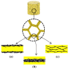
Figure 1
Figure 1
Polymer nanocomposite foams with three different internal structures: (a) coating graphene onto polymeric foams; (b) graphene foam coated with a polymer layer; (c) graphene dispersed in the polymer foam skeleton. Reproduced with permission from [23]. Copyright 2019 Elsevier Ltd.
Figure 2
Figure 2
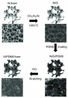
Fabrication process of polymer-based graphene foams. Reproduced with permission from [24]. Copyright 2013 John Wiley & Sons Inc.
Figure 3
Figure 3
Illustration for preparation of the reduced graphene oxide (RGO)-coated PU sponge. Reproduced with permission from [25]. Copyright 2018 Elsevier Ltd.
Figure 4
Figure 4
Synthesis of graphene foam (GF) coated with poly(methyl methacrylate) (PMMA). Reproduced with permission from [29]. Copyright 2011 Springer Nature.
Figure 5
Figure 5
SEM images of graphene foam/PDMS composites with different porosities: (a) 9.3%; (b) 28.9%; (c) 51.5%; (d) 73.2%; (e) 90.8%. Reproduced with permission from [32]. Copyright 2016 Elsevier Ltd.
Figure 6
Figure 6
Schematic illustration of the supercritical CO2 foaming process [37].
Figure 7
Figure 7
Fabrication of graphene–PSt foam using compression molding and then the salt-leaching method. Reproduced with permission from [47]. Copyright 2012 Royal Society of Chemistry.
Figure 8
Figure 8
(a) EMI SEtotal of graphene–PMMA nanocomposite foams with different volume contents of graphene from 8 to 12 GHz. (b) The values of SEtotal, SEA, and SER at 9 GHz with 0 vol%, 0.6 vol%, 0.8 vol%, and 1.8 vol% graphene. Reproduced with permission from [48]. Copyright 2011 American Chemical Society.
Figure 9
Figure 9
The EMI SEtotal, SEA, and SER of GPS045 (a) and GPS027 (b) in X-band. Reproduced with permission from [47]. Copyright 2012 Royal Society of Chemistry.
Figure 10
Figure 10
(a) The conductivity of composite foams versus weight percentage of loaded f-G. Inset: plot of log conductivity versus log (p − pc)/pc for the composite foams. (b) EMI SE for f-G/PVDF foam composites in X-band. Reproduced with permission from [42]. Copyright 2011 John Wiley & Sons Inc.
Figure 11
Figure 11
SEM images of graphene–PEI nanocomposite foams at different graphene loadings (left); The EMI SSE of graphene–PEI nanocomposite solids and foams at 9.6 GHz (right). Reproduced with permission from [45]. Copyright 2013 American Chemical Society.
Figure 12
Figure 12
Schematic operation for nonsolvent-induced phase separation (NIPS) by soaking the casting film of PAA/rGO in a coagulant bath (a) and the formation process of PAA/rGO composite foams (b). Reproduced with permission from [50]. Copyright 2015 Royal Society of Chemistry.
Figure 13
Figure 13
EMI shielding efficiency of different PU/rUL-GO composite foams at different frequencies. Reproduced with permission from [41]. Copyright 2016 Royal Society of Chemistry.
Figure 14
Figure 14
Overall fabrication process of PUG foams, including dip coating GO sheets onto the PU framework and then hydrothermally reducing them with hydrazine vapor. Reproduced with permission from [53]. Copyright 2016 American Chemical Society.
Figure 15
Figure 15
Schematic of the procedure for fabricating graphene–PDMS foam composites. The scale bars are 500 μm. Reproduced with permission from [31]. Copyright 2013 John Wiley & Sons Inc.
Figure 16
Figure 16
(a) EMI shielding effectiveness of graphene–PDMS foam composites with different electrical conductivities measured in the frequency range of 8–12 GHz (X-band). (b) Comparison of SEtotal, SEA, and SER of graphene–PDMS foam composites with different electrical conductivities at a frequency of 9 GHz. Reproduced with permission from [31]. Copyright 2013 John Wiley & Sons Inc.
Figure 17
Figure 17
Comparison of mean values of SET, SEA, and SER over the whole frequency range of (a) GF/PDMS composites with different porosities and (b) GF/CNT/PDMS composites with different CNT contents. Reproduced with permission from [32]. Copyright 2016 Elsevier Ltd.
Figure 18
Figure 18
(a) Schematic procedure for the preparation of GF/PEDOT:PSS composites; EMI SEs of composites with different compositions: (b) SEA and SER and (c) summary of SEs, SSEs, and SSEs normalized by area density as a function of mass ratio of PEDOT:PSS to GF. Reproduced with permission from [56]. Copyright 2017 American Chemical Society.

Similar articles

Cited by

References

    1. Shahzad F., Alhabeb M., Hatter C., Anasori B., Hong S., Koo C., Gogotsi Y. Electromagnetic interference shielding with 2D transition metal carbides (MXenes) Science. 2016;353:1137–1140. doi: 10.1126/science.aag2421. - DOI - PubMed
    1. Choudary V., Dhawan S.K., Saini P. EMI Shielding Theory and Development of New Materials. Research Signpost; Kerala, India: 2012. Polymer based nanocomposites for electromagnetic interference (EMI) shielding.
    1. Fu S., Sun Z., Huang P., Li Y., Hu N. Some basic aspects of polymer nanocomposites: A critical review. Nano Mater. Sci. 2019;1:2–30. doi: 10.1016/j.nanoms.2019.02.006. - DOI
    1. Shen X., Zheng Q., Kim J. Rational design of two-dimensional nanofillers for polymer nanocomposites toward multifunctional applications. Prog. Mater Sci. 2021;115:100708. doi: 10.1016/j.pmatsci.2020.100708. - DOI
    1. Yang Y., Gupta M.C., Dudley K., Lawrence R. Conductive Carbon Nanofiber–Polymer Foam Structures. Adv. Mater. 2005;17:1999–2003. doi: 10.1002/adma.200500615. - DOI

LinkOut - more resources