. 2023 Jul 31:30:142-153.
doi: 10.1016/j.bioactmat.2023.07.019. eCollection 2023 Dec.

Micromolded honeycomb scaffold design to support the generation of a bilayered RPE and photoreceptor cell construct

Affiliations

Micromolded honeycomb scaffold design to support the generation of a bilayered RPE and photoreceptor cell construct

In-Kyu Lee et al. Bioact Mater. .

Abstract

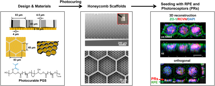
Age-related macular degeneration (AMD) causes blindness due to loss of retinal pigment epithelium (RPE) and photoreceptors (PRs), which comprise the two outermost layers of the retina. Given the small size of the macula and the importance of direct contact between RPE and PRs, the use of scaffolds for targeted reconstruction of the outer retina in later stage AMD and other macular dystrophies is particularly attractive. We developed microfabricated, honeycomb-patterned, biodegradable poly(glycerol sebacate) (PGS) scaffolds to deliver organized, adjacent layers of RPE and PRs to the subretinal space. Furthermore, an optimized process was developed to photocure PGS, shortening scaffold production time from days to minutes. The resulting scaffolds robustly supported the seeding of human pluripotent stem cell-derived RPE and PRs, either separately or as a dual cell-layered construct. These advanced, economical, and versatile scaffolds can accelerate retinal cell transplantation efforts and benefit patients with AMD and other retinal degenerative diseases.

Keywords: Microfabrication; Retina; Scaffolds; Stem cells; Tissue engineering.


Conflict of interest statement

D.M.G. is an inventor on patents related to this work filed by the Wisconsin Alumni Research Foundation, Madison, WI (no. 9,752,119, filed 29 April 2016, published 5 September 2017) (no. 9,328,328, filed 24 August 2010, published 3 May 2016). D.M.G., Z.M., M.J.P., and S.G. are inventors on a patent filed by the Wisconsin Alumni Research Foundation, Madison, WI (no. 2017/0226459, filed 5 February 2016, published 10 August 2017). D.M.G., Z.M., M.J.P., S.G., and I.-K.L. are inventors on patents filed by the Wisconsin Alumni Research Foundation, Madison, WI (no. 2020/0010799, filed 9 July 2019, published 01 September 2020) (serial no. 17/769549, filed 10 October 2020, pending). D.M.G. and M.J.P. have an ownership interest in Opsis Therapeutics LLC, which has licensed the technology to generate 3D retinal organoids from pluripotent stem cell sources reported in this publication. The authors declare that they have no other competing interests.

Figures

Image 1
Graphical abstract
Fig. 1
Fig. 1
a-d) Schematic illustration of the honeycomb-shaped microscaffold showing a) a tilted top view, b) a tilted bottom view, c) a cross-sectional view, and d) a top view, respectively. The hexagonal prism-shaped cell capture wells (white in color) are designed to have a large volume (i.e., 40 μm in depth and 48 μm in length for each side of the hexagon) for capturing and retaining both RPE and PR cells in the wells, and the cylinder-shaped fluid channels (orange in color) are tailored to be narrow enough (i.e., ∼4 μm) to prevent the seeded cells from migrating through the channels while still supporting cell functions during scaffold degradation. e) Schematic of the procedure for generating a Si master, a hybrid-PDMS stamp, and a photocurable PGS-based microscaffold. (i) Fluid channel- and (ii) cell capture well-etching processes for creating a Si master. (iii) Hybrid-PDMS stamp demolded from the Si master. (iv) The hybrid-PDMS stamp is mounted on liquid PGS on a Si wafer, and after photocuring of the PGS, the stamp is demounted from the scaffold via sonication in 99.97% IPA solution. (v) Completed honeycomb-shaped microscaffold.
Fig. 2
Fig. 2
SEM images of the fabricated a) Si master and b) hybrid-PDMS stamp showing (i) a tilted view, (ii) a top view, and (iii) a cross-sectional view, respectively. The inset images show a magnified view of the microstructures of the fabricated Si master mold and hybrid-PDMS stamp.
Fig. 3
Fig. 3
Synthesis and characterization of the photocurable PGS prepolymer and photocured PGS. a) The synthesis schemes of the photocurable PGS prepolymer. The PGS prepolymer was first synthesized by polycondensation of glycerol and sebacic acid. Thereafter, the photocurable PGS prepolymer was synthesized by esterification between hydroxyl groups on PGS and methacrylic anhydride. b) Under UV at 365 nm and initiated by DMPA, the photocurable PGS prepolymer can be efficiently cured within 5 min, with or without the addition of GMA. c) Stress-strain curves of the photocured PGS with or without 10 wt% GMA. The result indicated that the addition of GMA significantly increased the Young's modulus of the photocured PGS from 1.07 MPa to 4.62 MPa due to its higher crosslinking density.
Fig. 4
Fig. 4
a) Schematic illustration of the new stamp demounting process. In order to facilitate the scaffold delamination, the stamp was cut horizontally and then vertically using a razor blade, and then sonication-treated in isopropanol (IPA) for 4 h. b) SEM images of the fabricated microscaffold: (i) tilted view (the inset shows a low-magnification photographic image of the fabricated microscaffold held with a tweezer), (ii) magnified view of the scaffold, (iii) magnified view of the wall of a scaffold cell capture well, (iv) cross-sectional view, (v) top view, and (vi) bottom view.
Fig. 5
Fig. 5
Microscaffolds seeded with RPE and PRs cells. a) High and b) low magnification brightfield images of microscaffolds before and 24 h after being seeded with hPSCs-derived RPE (RPE) cells. Scale bars: a) 100 μm and b) 500 μm. c) Microscaffolds seeded with RPE cells and analyzed after 7 days by immunocytochemistry staining for ZO-1 (green), MITF (red), and DAPI for nuclei (blue). Scale bars, in c and c’ are 100 μm. c’) magnified view of the dashed square showed in c showing ZO-1 immunostaining (upper c’ panel) and a merged image (lower c’ panel). d) Tilted view of a 3D confocal reconstruction showing RPE cells 7 days after seeding on the microscaffold. Scale bar: 100 μm. e-g) Side views of 3D reconstructed images showing the surface of a single honeycomb well covered by a layer of RPE cells 7 days after seeding. Scale bar: 20 μm. h) Violin plots showing the distribution of the number of RPE cells (in blue) or PRs (in red) within individual HC wells 7 days after seeding with 4 × 105 RPE cells/transwell or 3.5 × 106 PRs/transwell. The box plots in the middle of each violin plot delineate the first and third quartiles of the distribution and the central white dot in each box plot indicates the median value. i) WA09-CRX+/tdTomato hPSC-derived retinal organoid after 120 days of differentiation. Scale bar: 500 μm. j) Dissociated cells from CRX17-tdTomato + retinal organoids. Scale bar: 100 μm. k) High and l) low magnifications of live cell fluorescence microscopy images of a microscaffold seeded with PRs from dissociated CRX+/tdTomato organoids two days after seeding. Scale bars: k) 100 μm and l) 500 μm. m) Maximum intensity projection (Max IP) image of a microscaffold seeded with CRX+/tdTomato PRs cells, collected 7 days after seeding and immunostained with recoverin (RCVN, green) and tdTomato (red). Scale bar: 100 μm. n) Tilted view of a 3D confocal reconstruction showing CRX+/tdTomato PRs 7 days after being seeded on a microscaffold. DAPI was used to counterstain the nuclei (blue). Scale in x-axis: 50 μm; in z-axis; 40 μm; in y-axis: 50 μm.
Fig. 6
Fig. 6
Seeding of microscaffolds with RPE and PR cells. a) Brightfield images of microscaffolds 24 h after being seeded with 400K RPE cells. b,c) Live cell fluorescence microscopy images of an RPE-coated microscaffold 24 h after seeding with PRs (red fluorescent clusters). Scale bars: a,b) 100 μm and c) 500 μm. d) MaxIP image of microscaffold seeded with both RPE (Mitf + cells) and PRs (RCVN + cells) 7 days after PR seeding. DAPI was used to counterstain the nuclei (blue). Scale bar: 50 μm. e) Side views of 3D reconstructed images from (d). Scale bar: 50 μm. f) High resolution confocal images of PR cells (RCVN + cells) seeded within wells coated with a continuous layer of RPE (ZO-1+ cells). g) Side views of 3D reconstructed images shown in (f). Scale bar: 50 μm. h) Orthogonal projections from the same wells shown in (f) and (g). i) Violin plots showing the distribution of the number of RPE cells (in blue) or PRs (in red) within individual HC wells 7 days after the generation of bilayered RPE:PR cell constructs. The box plots in the middle of each violin plot delineate the first and third quartiles of the distribution and the central withe dot in each box plot indicates the median value.

References

    1. Lakkaraju A., Umapathy A., Tan L.X., Daniele L., Philp N.J., Boesze-Battaglia K., Williams D.S. The cell biology of the retinal pigment epithelium. Prog. Retin. Eye Res. 2020 - PMC - PubMed
    1. Strauss O. The retinal pigment epithelium in visual function. Physiol. Rev. 2005;85(3):845–881. - PubMed
    1. Taylor A.W. Ocular immune privilege and transplantation. Front. Immunol. 2016;7:37. - PMC - PubMed
    1. Hassell J.B., Lamoureux E.L., Keeffe J.E. Impact of age related macular degeneration on quality of life. Br. J. Ophthalmol. 2006;90(5):593–596. - PMC - PubMed
    1. Rein D.B., Wittenborn J.S., Zhang X., Honeycutt A.A., Lesesne S.B., Saaddine J. Forecasting age-related macular degeneration through the year 2050: the potential impact of new treatments. Arch. Ophthalmol. 2009;127(4):533–540. - PubMed

LinkOut - more resources