Review
. 2023 Aug 17;17(1):53.
doi: 10.1186/s13036-023-00372-6.

Cancer-on-chip: a 3D model for the study of the tumor microenvironment

Affiliations
Review

Cancer-on-chip: a 3D model for the study of the tumor microenvironment

Elisa Cauli et al. J Biol Eng. .

Abstract

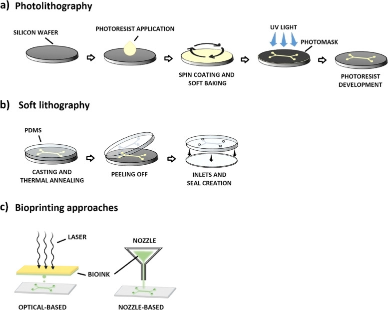
The approval of anticancer therapeutic strategies is still slowed down by the lack of models able to faithfully reproduce in vivo cancer physiology. On one hand, the conventional in vitro models fail to recapitulate the organ and tissue structures, the fluid flows, and the mechanical stimuli characterizing the human body compartments. On the other hand, in vivo animal models cannot reproduce the typical human tumor microenvironment, essential to study cancer behavior and progression. This study reviews the cancer-on-chips as one of the most promising tools to model and investigate the tumor microenvironment and metastasis. We also described how cancer-on-chip devices have been developed and implemented to study the most common primary cancers and their metastatic sites. Pros and cons of this technology are then discussed highlighting the future challenges to close the gap between the pre-clinical and clinical studies and accelerate the approval of new anticancer therapies in humans.

Keywords: Cancer-on-chip; Metastasis; Microfluidics; Organ-on-chip; Pre-clinical models; Tumor microenvironment.


Conflict of interest statement

The authors declare no competing interests.

Figures

Fig. 1
Fig. 1
The carcinogenesis and the metastatic cascade. The carcinogenesis and the metastatic cascade are complex processes that comprise the mechanisms associated with the primary tumor and its colonization of other organs (metastasis). The first phase is the primary tumor growth (1) followed by the generation of new capillary blood vessels (2), a crucial step for tumor progression and invasion. Once the cancer cells undergo the epithelial-to-mesenchymal transition (EMT), they acquire the metastatic phenotype (3), which allows the cells to move and enter the blood vessels through intravasation (4) and leave them (extravasation, 5) when they reach distant organs, the metastatic sites (6)
Fig. 2
Fig. 2
The two main microfabrication techniques used to generate organs-on-chip. a Photolithography is the core microfabrication technique used to transfer micro- and nanoscale patterns to photosensitive materials by optical radiation. A silicon wafer is used as support for the photo-sensitive material, which is generally called photoresist. After its application on the wafer’s surface, the wafer is spin-coated to obtain a thin uniform film of the photoresist, which is then brought in contact with a photomask that reproduces the desired pattern. The photoresist crosslink in the parts exposed to high-intensity ultraviolet (UV) light; while the covered photoresist is removed by a chemical agent. The negative design of the mask is now reproduced on the silicon master. b Soft lithography allows the fabrication of elastomeric molds using a replica molding technique. The PDMS is cast against the bas-relief pattern of the silicon master photoresist. After a thermal phase, the resulting substrate is peeled off showing the 3D pattern of the original master. The microfluidic device is then generated by creating the needed features, e.g., the inlets, and by bonding it to a PDMS or glass slab. c 3D bioprinting constructs microfluidic devices using a fast and automated process. In the bioprinting nozzle-based approach, the bioink is extruded through a nozzle moved by a computer-controlled arm to create 3D shapes. Superior resolutions are obtained using optical-based approaches where laser exposure solidifies the bioink through a crosslinking reaction
Fig. 3
Fig. 3
Examples of breast cancer-on-chips. a Bifurcated chip to study a possible solution for the acidification of the primary tumor environment. (i) Design of the microfluidic device: the upper chambers are loaded with CaCO3 nanoparticles able to neutralize the acidification of the TME. (ii) Chip setup. Pipette tips are used to feed the upper and lower chambers, while the middle channel (which ensures the separation between the control and experimental compartments) is connected to a syringe pump. Adapted from [144] with permissions from Scientific Reports. b Organ-on-chip model to analyze the tissue-specific breast cancer extravasation. (i) Schematic illustration of the extravasation chip with the Side 2 view highlighted. (ii) Z-stack projection images of Side 2 view showing HUVEC-C endothelial monolayers (green), extravasated (arrowhead), and associated (arrow) human breast cancer cells (MDA-MB-231, red) into the lung, liver, or breast microenvironments. Adapted from [145] with permissions from Biotechnology & Bioengineering. c Miniaturized bone-on-a-chip to study breast cancer bone metastasis. (i) Schematic of the simultaneous-growth-and-dialysis mechanism. Low-molecular-weight nutrients and metabolic waste move continuously through the dialysis membrane. While large bone matrix-building proteins accumulate in the bottom chamber contributing to the spontaneous formation of the osteoblastic tissue. (ii) Exploded view of the bone-on-a-chip. (iii) Injected inks highlight the central circular area of the assembled chip. Dialysis occurs in this space. Adapted from [146] with permissions from Small
Fig. 4
Fig. 4
Examples of lung cancer-on-chips. a Microfluidic chip for the study of the role of the stromal cells in tumorigenesis. (i) An in vivo-simulating representation of the TME was achieved by integrating into the same microfluidic device stromal cells, fibroblasts, and endothelial cells surrounded by a 3D collagen matrix with a channel for the continuous flow of the culture medium. (ii) Overview of the main components interacting with the microfluidic device. Adapted from [153] with permissions from Scientific Reports. b Microfluidic device to recapitulate the metastatic brain niche. (i) Representation of the bTME composed of BM-NSCLC, cerebral microvascular endothelial cells, and primary human brain astrocytes. (ii) Configuration of the seven-channel microfluidic device with its cross-section showing where each cell type is cultured. Adapted from [154] with permissions from Advanced Science. c Multi-organs-on-a-chip for the study of different metastatic sites. (i) Schematic illustration of the multi-organs-on-a-chip comprising the primary site of cancer (the lung, in purple) and the three distant organs (inlet 3, inlet 4, and inlet 5). (ii) Representation of the chip lung structure, where a membrane divides the air compartment from the blood one. Lung cancer cells are co-cultured with human bronchial epithelial cells on the upper side of the membrane, while stromal cells (microvascular endothelial cells, fibroblasts, and macrophages) are seeded on the lower side. Metastatic lung cancer cells move along the blood channel to reach distant organs, the brain, bone, and the liver. (iii) Overview of the chip structure composed of three main layers and two microporous membranes. Adapted with permission from [136]. Copyright 2016 American Chemical Society
Fig. 5
Fig. 5
Examples of pancreatic cancer-on-chips. a Pancreas-on-a-chip to model fibrosis-related disorders. (i) Pancreatic ductal epithelial cells (PDCEs) were cultured inside the single-channel chip (ii) together with pancreatic islets (iii) to monitor the Cystic Fibrosis Transmembrane Conductance Regulator (CFTR) function. Adapted from [158] with permissions from Nature Communications. b HepaChip® for the diagnosis and prognosis of PDAC. (i) Image of the chip with the 8 culture chambers. The electrodes and ridges present in each chamber are shown together with flow velocity and trajectory simulation. (ii) Live/Dead of the PDAC cells after 146 h of culture inside the HepaChip®. Adapted from [159] with permissions from Scientific Reports. c Organ-on-chip to model the invasion of PDAC tumor cells to blood vessels. (i) Two hollow cylindrical channels in the microfluidic device mimic the blood vessel and the pancreatic cancer duct, respectively. Endothelial cells (HUVEC) were seeded in the perfusable vessel, while pancreatic cells were cultured in the cancer duct. (ii) Representation of the average invasion distance of the PDAC cell line PD7591 when an FBS gradient is established and with/without the HUVEC cells. Speed migration is increased when the HUVECs are present. Adapted from [161] with permissions from Science Advances
Fig. 6
Fig. 6
Examples of colon cancer-on-chips. a The vascularized micro-tumors (VMTs) are composed of 3 tissue chambers (T1-3), hosting CRC cells, fibroblasts, and endothelial cells. There is also a pressure regulator (PR) to prevent the gel rupture, two loading ports (L1-2), and two medium inlets and outlets (M1-2). The entire structure is bonded onto a bottomless 96-well plate. Reproduced from [172] with permission from The Royal Society of Chemistry. b Schematic representation of the microfluidic device for tumor and fibroblast cells co-culture composed of seven channels: three to host cells and four for the media. Reproduced with permission [177] Copyright 2016, Jeong et al. c The CRC-on-chip (image courtesy of Emulate, Inc.) is composed of two channels: at the top, the epithelial channel (1), hosting epithelial and CRC cells (3); at the bottom, the endothelial channel (2), hosting HUVEC cells (4). The two channels are divided by a porous membrane (5). Reproduced with permission [174]. Copy-right Strelez et al., 2021. d Metastasis-on-a-chip (MOC). To provide an equal flow into all device chambers, the media was perfused from the colorectal compartment and then bifurcated twice to the endothelial (E), lung (Lu), and liver (Li) constructs. Reproduced with permission [135]. Copyright 2019, John Wiley and Sons
Fig. 7
Fig. 7
Examples of liver cancer-on-chips. a Schematic design of the microfluidic device. (i) The left channel was used to generate the hypoxic gradient (red fluorescent image), flanked by the culture compartment composed of three adjacent channels. (ii) Image of the co-culture compartments. Reproduced from [182] with permission from the Chinese Journal of Analytical Chemistry. b Cholangiocarcinoma-on-chip to detect the CTCs in the human bile. (i) Image of the chip with its compartments. Upper module: A, sample loading chamber; B, membrane-type micromixers/micropumps; P, PBS chamber; W, waste outlet. Lower module: C, membrane-type micromixers/micropumps; D, paraformaldehyde chamber; E, Triton X-100 chamber; F - G, first and secondary antibody chambers, respectively; H, DAPI/Hoechst stain chamber; P, PBS chamber; W, waste outlet. (ii) Schematic representation of the cell capture, washing, collection, and immunofluorescence (IF) staining and analysis on-chip. Reproduced from [183] Copyright Hung et al., 2017
Fig. 8
Fig. 8
Overview of the possible cancer-on-chips applications. In general, these microfluidic devices can be used to study all cancer features and stages, to perform anti-cancer drug screening in terms of safety and efficacy, and to implement personalized medicine using patient-derived cells
Fig. 9
Fig. 9
Summary of pros and cons of cancer-on-chips. Many pros are identified for the cancer-on-chip technology when compared to the conventional in vitro and in vivo models. However, acceptance of cancer-on-chip as a pre-clinical tool has several drawbacks that must be solved

References

    1. Kocarnik JM, Compton K, Dean FE, Fu W, Gaw BL, Harvey JD, Henrikson HJ, Lu D, Pennini A, Xu R, et al. Cancer incidence, mortality, years of life lost, years lived with disability, and disability-adjusted life years for 29 cancer groups from 2010 to 2019: a systematic analysis for the global burden of disease study 2019. JAMA Oncol. 2022. 10.1001/jamaoncol.2021.6987. - PMC - PubMed
    1. Soerjomataram I, Bray F. Planning for tomorrow: global cancer incidence and the role of prevention 2020–2070. Nat Rev Clin Oncol. 2021 doi: 10.1038/s41571-021-00514-z. - DOI - PubMed
    1. Winkle M, El-Daly SM, Fabbri M, Calin GA. Noncoding RNA therapeutics - challenges and potential solutions. Nat Rev Drug Discov. 2021 doi: 10.1038/s41573-021-00219-z. - DOI - PMC - PubMed
    1. Davis-Marcisak EF, Deshpande A, Stein-O’Brien GL, Ho WJ, Laheru, D, Jaffee EM, Fertig EJ, Kagohara LT. From bench to bedside: single-cell analysis for cancer immunotherapy. Cancer Cell. 2021. 10.1016/j.ccell.2021.07.004. - PMC - PubMed
    1. Propper DJ, Balkwill FR. Harnessing Cytokines and Chemokines for Cancer Therapy. Nat Rev Clin Oncol. 2022 doi: 10.1038/s41571-021-00588-9. - DOI - PubMed

LinkOut - more resources