Review
. 2023 Aug 8:11:1185841.
doi: 10.3389/fbioe.2023.1185841. eCollection 2023.

Biofabrication of functional bone tissue: defining tissue-engineered scaffolds from nature

Affiliations
Review

Biofabrication of functional bone tissue: defining tissue-engineered scaffolds from nature

Aaqil Rifai et al. Front Bioeng Biotechnol. .

Abstract

Damage to bone leads to pain and loss of movement in the musculoskeletal system. Although bone can regenerate, sometimes it is damaged beyond its innate capacity. Research interest is increasingly turning to tissue engineering (TE) processes to provide a clinical solution for bone defects. Despite the increasing biomimicry of tissue-engineered scaffolds, significant gaps remain in creating the complex bone substitutes, which include the biochemical and physical conditions required to recapitulate bone cells' natural growth, differentiation and maturation. Combining advanced biomaterials with new additive manufacturing technologies allows the development of 3D tissue, capable of forming cell aggregates and organoids based on natural and stimulated cues. Here, we provide an overview of the structure and mechanical properties of natural bone, the role of bone cells, the remodelling process, cytokines and signalling pathways, causes of bone defects and typical treatments and new TE strategies. We highlight processes of selecting biomaterials, cells and growth factors. Finally, we discuss innovative tissue-engineered models that have physiological and anatomical relevance for cancer treatments, injectable stimuli gels, and other therapeutic drug delivery systems. We also review current challenges and prospects of bone TE. Overall, this review serves as guide to understand and develop better tissue-engineered bone designs.

Keywords: 3D bioprinting; biofabrication; biomaterials; bone tissue; growth factor; hydrogel; organoid; tissue engineering and regenerative medicine.


Conflict of interest statement

The authors declare that the research was conducted in the absence of any commercial or financial relationships that could be construed as a potential conflict of interest.

Figures

FIGURE 1
FIGURE 1
Quad of Tissue Engineering: The biomaterial scaffold, regenerative cells, instructive morphogens/cytokines and fabrication modality.
FIGURE 2
FIGURE 2
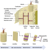
Bone anatomical structure. Bone ECM comprises organic components, inorganic components, cellular components and water. The outer layer of the bone is the periosteum, which consists of greater ECM and fewer cellular components. Cortical bone is found in the diaphysis and is composed of osteons. Trabecular bone is in the metaphysis and epiphysis while endosteum is the inner membrane formed by type III collagen and osteo-progenitor cells. Bone marrow is involved in bone repair and regeneration. Further, bone ECM consists of organic components, inorganic components, cellular components and water (Alvarez and Nakajima, 2009; Fraile-Martínez et al., 2021). Adapted from Henkel et al. (2013).
FIGURE 3
FIGURE 3
The multicellular nature of bone. Healthy bone is a result of balanced activity between osteoclasts and osteoblasts, which is regulated by different signalling pathways, transcription factors and cytokines along with other bone cells; osteocytes, osteomacs and bone lining cells (Takahashi et al., 1999; Guihard et al., 2012; Kular et al., 2012; Fakhry et al., 2013; Florencio-Silva et al., 2015; Gu et al., 2017; Kenkre and Bassett, 2018).
FIGURE 4
FIGURE 4
Schematic representation of the bone remodelling process. Osteocytes detect changes within their microenvironment and activate the bone remodelling cycle. Bone lining cells create a raised canopy above the remodelling surface. Osteoclasts migrate to the damaged area and resorb the bone followed by bone formation by osteoblasts. Osteomacs remove the remaining debris in the resorption compartment. The osteoblasts that are trapped in the matrix differentiate into osteocytes. Finally, remaining osteoblasts either go through apoptosis or turn into bone lining cells as the new bone forms (Saunders and Truesdell, 2019). Adopted from Saunders and (Saunders and Truesdell, 2019).
FIGURE 5
FIGURE 5
Schematic of scaffold-free, scaffold-based and organ-on-a-chip systems for tissue engineering. The scaffold-free systems include a spheroid and organoid model. The scaffold-based system includes a hydrogel and bioink model. The organ-on-a-chip system includes a microfluidic model.
FIGURE 6
FIGURE 6
Gradient Fabrication. (A) Additive manufacturing is an intuitive approach to gradient fabrication, with methods including sequential layering, 3D printing, controlled fluidic mixing, and electrospinning. (B) Component redistribution approaches produce gradients from an initially homogenous distribution by controlled demixing via convective stretching, buoyancy, magnetic fields, or electric fields. (C) Controlled phase changes can also result in forming gradients from homogeneous starting materials, typically using graded exposure to heat or light. (D) Post modification involves the presentation of a gradient onto preformed materials, typically achieved by controlled component diffusion or photopatterning. Adopted with permission from Li et al. (2021).
FIGURE 7
FIGURE 7
FRESH printing of biological structures based on 3D imaging data and functional analysis of the printed parts. (A) A model of a human femur from 3D CT imaging data is scaled down and processed into machine code for FRESH printing. (B) The femur is FRESH printed in alginate, and after removal from the support bath, it closely resembles the model and is easily handled. (C) Uniaxial tensile testing of the printed femur demonstrates the ability to be strained up to 40% and elastically recover. (D) A model of a section of a human right coronary arterial tree from 3D MRI is processed at full scale into machine code for FRESH printing. (E) An example of the arterial tree printed in alginate (black) and embedded in the gelatin slurry support bath. (F) A section of the arterial trees printed in fluorescent alginate (green) and imaged in 3D to show the hollow lumen and multiple bifurcations. (G) A zoomed-in view of the arterial tree shows the defined vessel wall that is < 1 mm thick and the well-formed lumen. (H) A dark-field image of the arterial tree mounted in a perfusion fixture to position a syringe in the root of the tree. (I) A time-lapse image of black dye perfused through the arterial tree false-coloured at time points of 0–6 s to show flow through the lumen and not through the vessel wall. Scale bars, 4 mm (B), 10 mm (E), 2.5 mm (F), 1 mm (G), and 2.5 mm (H, I). Adopted with permission from Hinton et al. (2015).
FIGURE 8
FIGURE 8
Biofabrication of osteogenic tissues. Strategy no. 1: (A) Triangle-shaped tissue complexes were bioprinted using MSC/HUVEC spheroids and cultured for 3 days in GM and 12 days in OM. (B) Time-lapse images showing fusion of GFP+ spheroids up to day 15 (D15) after bioprinting. (C) An optical image showing the assembled tissue at day 15 after bioprinting. (D) Immunofluorescence staining (DAPI, CD31, F-actin, RUNX2, and DAPI + RUNX2) and (E) Alizarin red staining of the sectioned tissue. Strategy no. 2: (F) The final shape of the bioprinted tissue of osteogenic spheroids (cultured for 10 days in OM before bioprinting and 2 days in OM after bioprinting). Immunofluorescent images of (G) the bioprinted tissue and (H) confocal images of its histological sections stained for DAPI, CD31, and F-actin and (I) RUNX2 and DAPI + RUNX2. (J) Alizarin red staining of the tissue section. (K) Quantification of normalized RUNX2 intensity at different regions including the surface of assembled tissue, spheroid-spheroid interface, and core of spheroids (n = 50; **p < 0.01 and ***p < 0.001). (L) A representative heat map figure showing RUNX2/DAPI distribution in the surface of assembled tissue, spheroid-spheroid interface, and core of spheroids for strategy nos. 1 and 2. (M) BSP, COL1, ALP, RUNX2, and CDH2 gene expressions of 2D MSCs cultured in OM (control), 3D bioprinted tissues cultured in GM (control), and 3D bioprinted tissues cultured using strategy nos. 1 and 2 (n = 5; **p < 0.01 and ***p < 0.001). Adopted with permission from Ayan et al. (2020).
FIGURE 9
FIGURE 9
3D Bioprinting of vertebrae-shaped mechanically reinforced bioinks. (A) Description of multi‐tool 3D bioprinting process, 1) The outer geometry of a human vertebral body was scanned and next layers of 2) PCL filaments were deposited followed by deposition of the 3) MSC laden bioink, this was repeated in an orthogonal fashion to create a 4) composite vertebrae structure. (B) μCT analysis demonstrated the distribution of bioink and PCL within the composite vertebrae. Bioink + PCL filaments isolated using μCT, indicating the presence of bioink free channels conduits (blue regions) post‐printing. (C) Live/dead images of cells within the deposited bioink 1 h post‐printing, scale bar 1 mm. Adopted with permission from (Daly et al., 2016).

Similar articles

Cited by

References

    1. Albrektsson T., Johansson C. (2001). Osteoinduction, osteoconduction and osseointegration. Eur. Spine J. 10, S96–S101. 10.1007/s005860100282 - DOI - PMC - PubMed
    1. Alcala-Orozco C. R., Mutreja I., Cui X., Hooper G. J., Lim K. S., Woodfield T. B. (2022). Hybrid biofabrication of 3d osteoconductive constructs comprising mg-based nanocomposites and cell-laden bioinks for bone repair. Bone 154, 116198. 10.1016/j.bone.2021.116198 - DOI - PubMed
    1. Alvarez K., Nakajima H. (2009). Metallic scaffolds for bone regeneration. Mater. (Basel) 2 (3), 790–832. 10.3390/ma2030790 - DOI
    1. Amarasekara D. S., Kim S., Rho J. (2021). Regulation of osteoblast differentiation by cytokine networks. Int. J. Mol. Sci. 22 (6), 2851. 10.3390/ijms22062851 - DOI - PMC - PubMed
    1. Amarasekara D. S., Yun H., Kim S., Lee N., Kim H., Rho J. (2018). Regulation of osteoclast differentiation by cytokine networks. Immune Netw. 18 (1), e8. 10.4110/in.2018.18.e8 - DOI - PMC - PubMed

LinkOut - more resources