. 2023 Aug 24;17(1):55.
doi: 10.1186/s13036-023-00370-8.

Optimizing the fabrication of a 3D high-resolution implant for neural stimulation

Affiliations

Optimizing the fabrication of a 3D high-resolution implant for neural stimulation

Gal Shpun et al. J Biol Eng. .

Abstract

Background: Tissue-integrated micro-electronic devices for neural stimulation hold great potential in restoring the functionality of degenerated organs, specifically, retinal prostheses, which are aimed at vision restoration. The fabrication process of 3D polymer-metal devices with high resolution and a high aspect-ratio (AR) is very complex and faces many challenges that impair its functionality.

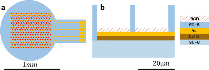
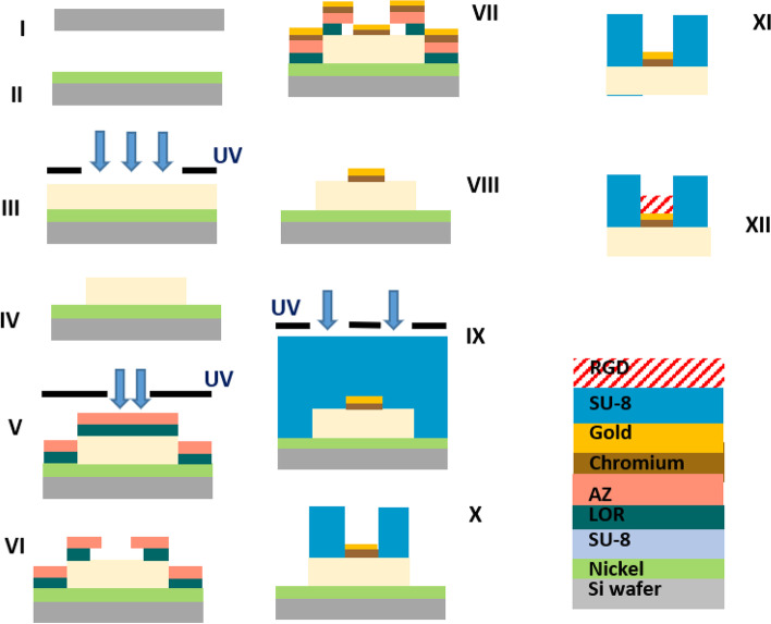
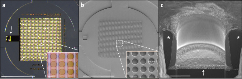
Approach: Here we describe the optimization of the fabrication process of a bio-functionalized 3D high-resolution 1mm circular subretinal implant composed of SU-8 polymer integrated with dense gold microelectrodes (23μm pitch) passivated with 3D micro-well-like structures (20μm diameter, 3μm resolution). The main challenges were overcome by step-by-step planning and optimization while utilizing a two-step bi-layer lift-off process; bio-functionalization was carried out by N2 plasma treatment and the addition of a bio-adhesion molecule.

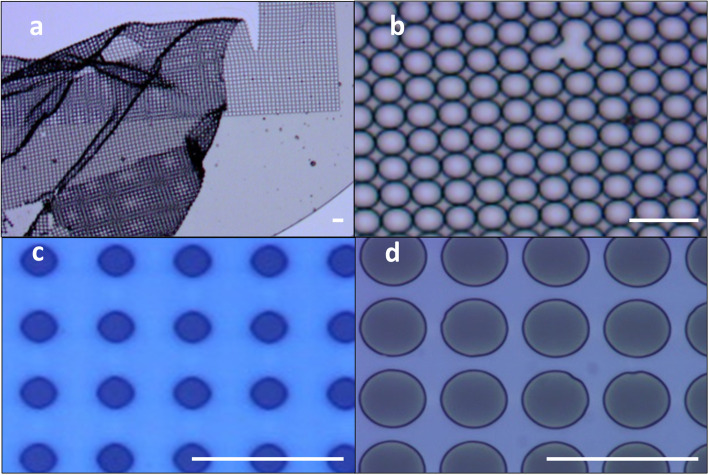
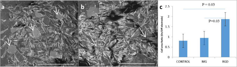
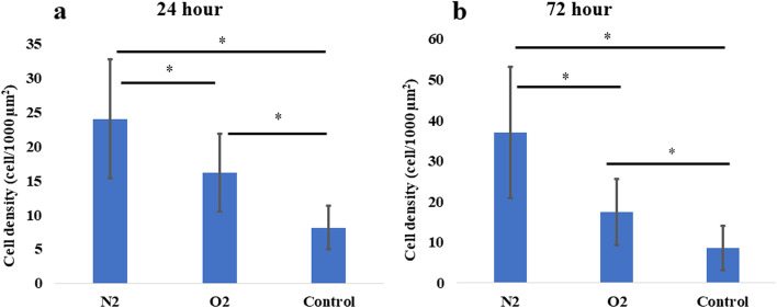
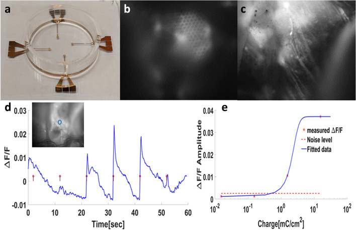
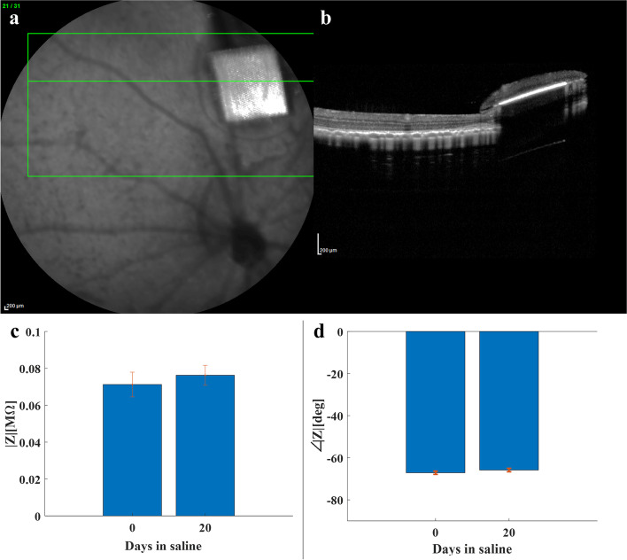
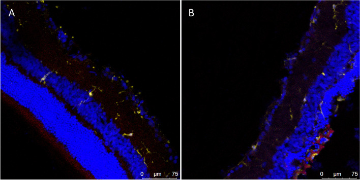
Main results: In-vitro and in-vivo investigations, including SEM and FIB cross section examinations, revealed a good structural design, as well as a good long-term integration of the device in the rat sub-retinal space and cell migration into the wells. Moreover, the feasibility of subretinal neural stimulation using the fabricated device was demonstrated in-vitro by electrical activation of rat's retina.

Conclusions: The reported process and optimization steps described here in detail can aid in designing and fabricating retinal prosthetic devices or similar neural implants.

Keywords: Bio-MEMS; Electrical Neuro-stimulation; Implantable devices; Neural interfaces; Retinal prostheses; SU-8 Photolithography.


Conflict of interest statement

The authors declare no conflict of interest.

Figures

Fig. 1
Fig. 1
Schematic illustration of the subretinal implant. The implant is composed of an SU-8 substrate and is designed as a 1 mm circular device constructed of 1,020 micro-wells (20 µm in both diameter and height) with a gold electrode at the bottom for neural activation. a) Top view of a complete implant structure. b) Side view, SU-8 micro-well-like structures; height 17 µm with the gold electrode at the bottom
Fig. 2
Fig. 2
Illustration of the final optimized fabrication process of a SU-8-gold high resolution, high aspect-ratio device. I) Ni thin-layer deposition. II) SU-8 spin coating, soft bake. III) UV exposure and PEB. IV) Development (PGMEA), curing and O2 plasma. V) LOR spin coating, baking, AZ photoresist spin coating, soft bake, and UV exposure. VI) AZ development (AZ351, AZ curing, and LOR development. VII) O2 plasma, Ar ion-milling, and Cr/Au (10/200 nm) metallization by thin-layer sputter deposition. VIII) Bi-layer lift-off (NMP). IX) 2nd SU8 layer spin coating, soft bake, and UV exposure. X) PEB, SU-8 development (PGMEA) and curing, XI) wet etch release (HNO3), and XII) RGD bio-functionalization by immersion
Fig. 3
Fig. 3
UV dose effect on the SU-8 patterning. a) An extreme underexposure dose leading to low mechanical strength and rupturing of the film. b) Underexposure dose leading to the expansion (22 µm) of the micro-wells and the fusion of adjacent wells. c) Extreme overexposure, leading to the closing and reduced diameter of the micro-wells. d) Optimal UV dose resulting in perfectly circularly shaped micro-wells of the desired diameter (20 µm). Scale bar - 50 µm in all figures
Fig. 4
Fig. 4
Optimization of gold microelectrode fabrication. a-d) A ruptured electrode with an "ear pattern" profile fabricated using the conventional AZ monolayer lift-off process and developed for 1 min. a) Top view SEM imaging (the Pt line is deposited for FIB/SEM and is not part of the fabrication process). b) FIB/SEM zoom in the cross section of the area demarcated with a rectangle revealing the continuity of the photoresist. c) Gold electrodes (80 µm diameter, 200 nm height) are broken and disconnected from the substrate. d) The electrodes’ edge cross section profile showing the “ear pattern” edge (arrows). eh) An intact electrode with a sharp profile fabricated using the bi-layer lift-off process (AZ and LOR) developed for 1 min, 5 min curing at 185 °C and another development phase of 1 min. ef) SEM imaging of the positive photoresist profile optimization process of a Bi-layer lift-off with LOR10B. e) An SEM image of the top view of a photoresist developed for 1 min. f) An FIB/SEM cross section and a zoom-in on the white rectangular area demarcated in) (e) (where the LOR10B was developed for 1 min, followed by an additional AZ curing step (120ºC). The photoresist has the desired undercut configuration, which is denoted by *. g) Intact gold electrodes (80 µm diameter, 200 nm height) with good attachment to the SU-8 surface. h) An electrode edge cross section profile showing the sharp edge (arrows)
Fig. 5
Fig. 5
Effect of various coatings on cell adhesion to gold electrodes. a-b) SEM image of ARPE cells seeded on gold electrodes (40 µm in diameter, white arrows), used to quantify the effect of various coatings on cell adhesion and the preference of gold electrodes without RGD (a) and with RGD (b); the scale bar = 200 µm. It can clearly be seen that although the cells tend to be repelled by bare gold electrodes (a), the cells tend to adhere to RGD-coated gold electrodes (b). c) The obtained adhesion of cells to gold electrodes for the various coatings defined as the prevention of the electrode area occupied by cells divided by the percentage of the area surrounding the electrodes occupied by cells. Values larger than the one obtained for the RGD coating reveal the cell’s preference for electrodes following this treatment, compared to the control
Fig. 6
Fig. 6
Effect of plasma surface treatment on SU-8 biocompatibility. Rat PRP cell density on N2 or O2 plasma-treated cured SU-8 (150W, 3 min) compared to not treated cured SU8. 24 h (a) and 72 h (b) post seeding. * Denotes p < 0.05
Fig. 7
Fig. 7
Images of a completed retinal implant (1mm in diameter) with a gold electrode array. a) Color image; the top view of a full SU-8-gold retinal implant; scale bar = 0.5mm. The insert is a zoom-in on the area demarcated by the rectangle (scale bar = 20µm). b) SEM images; the top view of the implant as in a); scale bar = 0.5mm. In the insert, a zoom-in on the area demarcated by the rectangular; scale bar = 20 µm. c) A FIB/SEM cross section image of the 3D well-like structure encapsulating the electrode; scale bar = 10µm. The black pillars are the SU-8 micro-wells walls (*) and the gold electrode (the white arrow). Scale bar = 10µm
Fig. 8
Fig. 8
Ex-vivo retinal stimulation proof of concept. a) The conceptual implant is placed in a dish with Ringer’s medium. b) A fluorescence image of the isolated retina harvested from transgenic GCaMP6f-Thy1 rats mounted on the implant. Arrows point to the micro-wells. c) The same as in b with the focal plane adjusted to show the fluorescent RGCs and axons (arrows). d) Average fluorescence change in response to electrical stimulation with increasing current density. e) Average fluorescence change in response to electrical stimulation with increasing charge density per phase, indicating an activation threshold below 0.156 mCcm2phase.
Fig. 9
Fig. 9
Integration of the implant in the sub-retinal space. Fundus image of the implanted device (white arrow) demonstrates the good placement near the optic disk; scale bar = 1mm. In the inset, an optical coherence tomography cross section reveals good integration of the implant in the sub-retinal space under the inner nuclear layer (INL), ONL – Outer Nuclear Layer; scale bar = 200µm
Fig. 10
Fig. 10
Histology of a flat mount retina implanted with the retinal device. a) Confocal imaging of the implanted retinal device (arrow) showing good anatomical integration in the subretinal space; scale bar = 100µm. The insert shows a high magnification of the micro-wells in the demarcated area showing proximity between the electrodes and bipolar cells entering the micro-wells; scale bar = 100µm. b) A cross section of the implanted retina showing the proximity between the implant and the BPC layer with some of the cells migrating towards the micro-wells (arrows). c) A cross-section at the micro-wells’ mid-height (reference point: the white dashed line in b) revealing the presence of bipolar cells within the micro-wells. Scale bar = 50µm. GC—ganglion cells, BPC—bipolar cells. Green—PKCα, blue—Nuclei
Fig. 11
Fig. 11
Implant Stability. a) OCT imaging performed 3 months following transplantation, revealing the structural integrity of the implant and its correct location in the subretinal space. b) The implant impedance at 1kHz was measured before and after a 20-day incubation, showing no significant changes in the electrodes’ impedance (p > 0.2)
Fig. 12
Fig. 12
IBA-1 staining—Cryosections of a control retina (a) and an implanted retina (b) stained for stained for Hoechst (blue), IBA-1 antibody (yellow) and Rhodamine B (red), which visualized the nuclei in the various retinal layers, microglia and microphages, and the implant respectively showing no difference in the immune system response

References

    1. Goetz GA, Palanker DV. Electronic approaches to restoration of sight. Rep Prog Phys. 2016;79:096701. - PMC - PubMed
    1. Yue L, Weiland JD, Roska B, Humayun MS. Retinal stimulation strategies to restore vision: Fundamentals and systems Lan. Prog Retin Eye Res. 2016;53:21–47. - PubMed
    1. Feiner R, et al. Engineered hybrid cardiac patches with multifunctional electronics for online monitoring and regulation of tissue function. Nat Mater. 2016;15:1–8. - PMC - PubMed
    1. Ha S, et al. Towards high-resolution retinal prostheses with direct optical addressing and inductive telemetry. J Neural Eng. 2016 doi: 10.1088/1741-2560/13/5/056008. - DOI - PubMed
    1. Charvet G, Rousseau L, Billoint O, Gharbi S, Rostaing J. BioMEA: A versatile high-density 3D microelectrode array system using integrated electronics. Biosens Bioelectron. 2010. 10.1016/j.bios.2010.01.001. - PubMed