Review
. 2023 Aug 14;13(8):815.
doi: 10.3390/bios13080815.

Hydrogel Bioelectronics for Health Monitoring

Affiliations
Review

Hydrogel Bioelectronics for Health Monitoring

Xinyan Lyu et al. Biosensors (Basel). .

Abstract

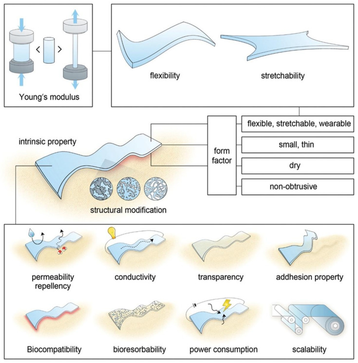
Hydrogels are considered an ideal platform for personalized healthcare due to their unique characteristics, such as their outstanding softness, appealing biocompatibility, excellent mechanical properties, etc. Owing to the high similarity between hydrogels and biological tissues, hydrogels have emerged as a promising material candidate for next generation bioelectronic interfaces. In this review, we discuss (i) the introduction of hydrogel and its traditional applications, (ii) the work principles of hydrogel in bioelectronics, (iii) the recent advances in hydrogel bioelectronics for health monitoring, and (iv) the outlook for future hydrogel bioelectronics' development.

Keywords: bioelectronics; biomaterials; health monitoring; hydrogel; wearable sensor.


Conflict of interest statement

The authors declare no conflict of interest.

Figures

Figure 1
Figure 1
Schematic illustration of the essential material properties of wearable bioelectronics. Reproduced with permission from Wiley-VCH, copyright 2019 [8].
Figure 2
Figure 2
(A) Schematic illustration of hydrogel-based cancer therapy. Reproduced with permission from Wiley-VCH, copyright 2022 [13]. (B) Schematic illustration of hydrogel-based gastric resident dosage forms. Reproduced with permission from Springer Nature, copyright 2017 [14].
Figure 3
Figure 3
(A) Photograph and schematic representation of a microfluidic device integrated with hydrogel. Reproduced with permission from Wiley-VCH, copyright 2019 [17]. (B) Illustration of a 3D-printed hydrogel in the shape of a heart and its fabrication processes. Reproduced with permission from Elsevier, copyright 2021 [18].
Figure 4
Figure 4
Images of self-assemble graphene hydrogel. Reproduced with permission from the American Chemical Society, copyright 2010 [38].
Figure 5
Figure 5
(A) Overview of a skin-based sensing platform. Reproduced with permission from Wiley-VCH, copyright 2019 [8]. (B) Schematic illustration of a skin–electrode interface model of on-skin electrodes. Reproduced with permission from Wiley-VCH, copyright 2021 [43]. (C) Schematic illustration of various analytes in sweat from (A). Reproduced with permission from Wiley-VCH, copyright 2019 [8].
Figure 6
Figure 6
(A) Schematic illustration of ionic conductive hydrogels’ formation, structure, and intermolecular interactions. Reproduced with permission from Wiley-VCH, copyright 2022 [44]. (B) Schematic illustration of the fabrication process of the nano-micelle zwitterionic hydrogels. Reproduced with permission from Elsevier, copyright 2020 [45].
Figure 7
Figure 7
(A) Description of the touch-based fingertip cortisol sensor. (B) Schematic interaction of cortisol in molecularly imprinted polymers (MIP) and lack of interaction in non-imprinted polymer (NIP). (C) Calibration curve of the electrochemical response of the MIP sensor to different cortisol concentrations in phosphate buffer solution (PBS) and in artificial sweat (AS). Reproduced with permission from Wiley-VCH, copyright 2021 [48].
Figure 8
Figure 8
(A) Schematic representation of the preparation of the skin-temperature-triggered smart milk-derived hydrogel (STSMH). (B) Infrared thermal images of the phase transition process of the STSMH hydrogel. (C) Visual presentation of the invisible cloak. Reproduced with permission from Elsevier, copyright 2022 [55]. (D) Illustration of multiple bonding interactions in the double-layer hydrogel and its ability to detect human motion. Reproduced with permission from the American Chemical Society, copyright 2022 [58].
Figure 9
Figure 9
(A) Schematic illustration of the wound dressing mechanism of the iTENG patch and its biomechanical energy harvesting mechanism. Reproduced with permission from Elsevier, copyright 2020 [65] (B) Schematic illustration of the hydrogel dressings for burn wound healing. (C) Schematic illustration of the adhesive mechanism of PSNC hydrogels. Reproduced with permission from the American Chemical Society, copyright 2021 [66]. (D) Schematic illustration of the fabrication and self-healing of the hydrogel. The red, green, black, orange, and blue dashed lines represent the hydration of the hydroxyl, cationic side chain, PEDOT:PSS, electrostatic interactions, and hydrogen bond, respectively. Reproduced with permission from Wiley-VCH, copyright 2020 [67]. (E) Schematic illustration and side view of a battery-free and wireless wound dressing for monitoring wound infection and electric-controlled drug delivery, and the schematic illustration of the electrically controlled drug delivery system. Reproduced with permission from Wiley-VCH, copyright 2021 [68].
Figure 10
Figure 10
(A) Schematic illustration of the hydrogel skin-like sensor system for a diabetic inflammation wound. Reproduced with permission from Wiley-VCH, copyright 2021 [78]. (B) Schematic illustration of the hydrogel-based ocular glucose sensor. (C) Schematic illustration of a smart contact lens for diabetic diagnosis and therapy. Reproduced with permission from the American Association for the Advancement of Science, copyright 2020 [79].
Figure 11
Figure 11
(A) Schematic illustration of an antibacterial oral GNT hydrogel. Reproduced with permission from the American Chemical Society, copyright 2022 [88]. (B) Schematic illustration of the hydrogel patch for on-demand fluoride delivery and real-time monitoring of the tooth microenvironment. Reproduced with permission from Springer Nature, copyright 2022 [89].
Figure 12
Figure 12
(A) Schematic illustration of rat vagus neuromodulation for blood pressure control. (B) Schematic illustration of ultrasound imaging of MGH/nerve interfaces. Reproduced with permission from Wiley-VCH, copyright 2022 [103]. (C) Top view of neurite outgrowth of PC12 and SCs co-cultures in 10 wt% PVA-SG. Reproduced with permission from Elsevier, copyright 2019 [105]. (D) Schematic illustration of the fabrication process of granular conductive hydrogels. Reproduced with permission from Wiley-VCH, copyright 2021 [106]. (E) Images of the mesh electrode with organoids and manipulation of metal forceps. (F) Images of connection between the mesh electrode and the Stim/Recording controller. Reproduced with permission from Elsevier, copyright 2022 [107].

Similar articles

Cited by

References

    1. Majumder S., Mondal T., Deen M.J. Wearable sensors for remote health monitoring. Sensors. 2017;17:130. doi: 10.3390/s17010130. - DOI - PMC - PubMed
    1. Nasiri S., Khosravani M.R. Progress and challenges in fabrication of wearable sensors for health monitoring. Sens. Actuator A Phys. 2020;312:112105. doi: 10.1016/j.sna.2020.112105. - DOI
    1. Zhang H., He R., Niu Y., Han F., Li J., Zhang X., Xu F. Graphene-enabled wearable sensors for healthcare monitoring. Biosens. Bioelectron. 2022;197:113777. doi: 10.1016/j.bios.2021.113777. - DOI - PubMed
    1. Kaur B., Kumar S., Kaushik B.K. Novel wearable optical sensors for vital health monitoring systems—A review. Biosensors. 2023;13:181. doi: 10.3390/bios13020181. - DOI - PMC - PubMed
    1. Heikenfeld J., Jajack A., Rogers J., Gutruf P., Tian L., Pan T., Li R., Khine M., Kim J., Wang J., et al. Wearable sensors: Modalities, challenges, and prospects. Lab Chip. 2018;18:217. doi: 10.1039/C7LC00914C. - DOI - PMC - PubMed

MeSH terms

LinkOut - more resources