. 2023 Aug 8;23(16):7016.
doi: 10.3390/s23167016.

Living-Neuron-Based Autogenerator

Affiliations

Living-Neuron-Based Autogenerator

Svetlana A Gerasimova et al. Sensors (Basel). .

Abstract

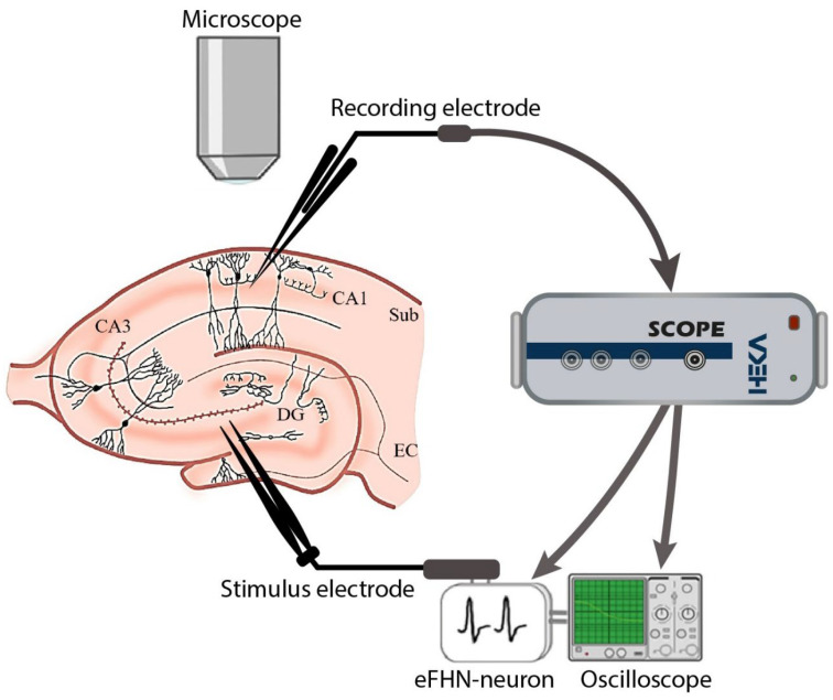
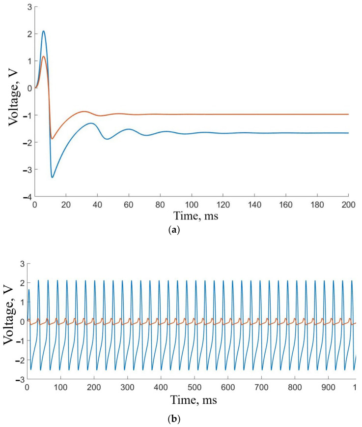
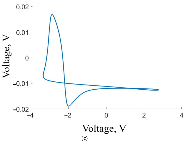
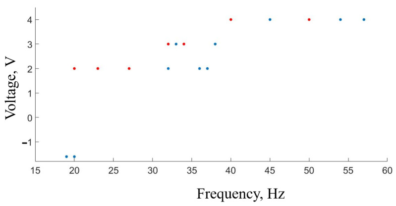
We present a novel closed-loop system designed to integrate biological and artificial neurons of the oscillatory type into a unified circuit. The system comprises an electronic circuit based on the FitzHugh-Nagumo model, which provides stimulation to living neurons in acute hippocampal mouse brain slices. The local field potentials generated by the living neurons trigger a transition in the FitzHugh-Nagumo circuit from an excitable state to an oscillatory mode, and in turn, the spikes produced by the electronic circuit synchronize with the living-neuron spikes. The key advantage of this hybrid electrobiological autogenerator lies in its capability to control biological neuron signals, which holds significant promise for diverse neuromorphic applications.

Keywords: autogenerator; close-loop control system; hippocampal slice; hybrid neural circuit; neuron-like oscillator.


Conflict of interest statement

The authors declare no conflict of interest.

Figures

Figure 1
Figure 1
Electronic neuron and generated pulses. (a) Block diagram illustrating the FHN neuron-like generator, comprising an external source, electronic circuit, cubic nonlinearity element, and signal amplifier. Input and output points are denoted by red dots. (b) Representative waveform of the 30 Hz output signal.
Figure 1
Figure 1
Electronic neuron and generated pulses. (a) Block diagram illustrating the FHN neuron-like generator, comprising an external source, electronic circuit, cubic nonlinearity element, and signal amplifier. Input and output points are denoted by red dots. (b) Representative waveform of the 30 Hz output signal.
Figure 2
Figure 2
Characteristics of the FitzHugh–Nagumo model. (a) Smooth nonlinear f(u) (blue) and non-smooth double-linear g(u) (red) functions. (b) Time series of the 33 Hz pulses of ν (red) and u (blue) variables with 25 ms duration.
Figure 3
Figure 3
Illustrative block scheme of the concept of resistive mutual coupling between FiztHugh–Nagumo circuit (FHN) and biological “oscillator”.
Figure 4
Figure 4
Experimental scheme with electrodes implanted in the hippocampal slice and pathway of signals from electronic neurons.
Figure 5
Figure 5
General illustration of the model neural activity. (a) Excitable regime corresponding to the initial system condition. (b) Time series of the neuron-like FHN signal (blue) and biological neuronal response (red) demonstrating a synchronous behavior. The “biological” signal is amplified by ten for better visualization. (c) Phase portrait of the voltages generated by the artificial and living neurons for d = 0.087 and k = 0.0223.
Figure 5
Figure 5
General illustration of the model neural activity. (a) Excitable regime corresponding to the initial system condition. (b) Time series of the neuron-like FHN signal (blue) and biological neuronal response (red) demonstrating a synchronous behavior. The “biological” signal is amplified by ten for better visualization. (c) Phase portrait of the voltages generated by the artificial and living neurons for d = 0.087 and k = 0.0223.
Figure 6
Figure 6
Illustration of neural activity. (a) Oscillograms demonstrating the signal from the neuron-like generator (blue) and the biological neuronal response (red), revealing synchronous spikes. (b) Phase portrait depicting the voltages generated by the electronic circuit and living neurons, providing a visual representation of their dynamical behavior and interaction.
Figure 7
Figure 7
Changing the neuron-like generator frequency as the signal amplitude is increased. The red dots have the following initial conditions: oscillatory regime, pulse amplitude of 2 V, and a frequency of 20 Hz. The blue dots have the following initial conditions: excited regime with a voltage of −1.5 V.
Figure 8
Figure 8
Examples of neuron responses. (a) Response on a positive peak, (b) response on a negative peak.

References

    1. FitzHugh R.A. Impulses and physiological states in theoretical models of nerve membrane. Biophys. J. 1961;1:445–466. doi: 10.1016/S0006-3495(61)86902-6. - DOI - PMC - PubMed
    1. Nagumo J., Arimoto S., Yoshizawa S. An active pulse transmission line simulating nerve axon. Proc. IRE. 1962;50:2061–2070. doi: 10.1109/JRPROC.1962.288235. - DOI
    1. Barba-Franco J.J., Gallegos A., Jaimes-Reátegui R., Gerasimova S.A., Pisarchik A.N. Dynamics of a ring of three unidirectionally coupled Duffing oscillators with time-dependent damping. Europhys. Lett. 2021;134:30005. doi: 10.1209/0295-5075/134/30005. - DOI
    1. Mikhaylov A.O., Komarov M.A., Levanova T.A., Osipov G.V. Sequential switching activity in ensembles of inhibitory coupled oscillators. Europhys. Lett. 2013;101:20009. doi: 10.1209/0295-5075/101/20009. - DOI
    1. Maksimenko V.A., Frolov N.S., Hramov A.E., Runnova A.E., Grubov V.V., Kurths J., Pisarchik A.N. Neural interactions in a spatially-distributed cortical network during perceptual decision-making. Front. Behav. Neurosci. 2019;13:220. doi: 10.3389/fnbeh.2019.00220. - DOI - PMC - PubMed

LinkOut - more resources