[Preprint]. 2023 Aug 15:arXiv:2308.07586v1.

Rapid model-guided design of organ-scale synthetic vasculature for biomanufacturing

Affiliations

Rapid model-guided design of organ-scale synthetic vasculature for biomanufacturing

Zachary A Sexton et al. ArXiv. .

Update in

Abstract

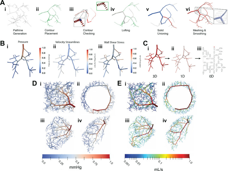
Our ability to produce human-scale bio-manufactured organs is critically limited by the need for vascularization and perfusion. For tissues of variable size and shape, including arbitrarily complex geometries, designing and printing vasculature capable of adequate perfusion has posed a major hurdle. Here, we introduce a model-driven design pipeline combining accelerated optimization methods for fast synthetic vascular tree generation and computational hemodynamics models. We demonstrate rapid generation, simulation, and 3D printing of synthetic vasculature in complex geometries, from small tissue constructs to organ scale networks. We introduce key algorithmic advances that all together accelerate synthetic vascular generation by more than 230 -fold compared to standard methods and enable their use in arbitrarily complex shapes through localized implicit functions. Furthermore, we provide techniques for joining vascular trees into watertight networks suitable for hemodynamic CFD and 3D fabrication. We demonstrate that organ-scale vascular network models can be generated in silico within minutes and can be used to perfuse engineered and anatomic models including a bioreactor, annulus, bi-ventricular heart, and gyrus. We further show that this flexible pipeline can be applied to two common modes of bioprinting with free-form reversible embedding of suspended hydrogels and writing into soft matter. Our synthetic vascular tree generation pipeline enables rapid, scalable vascular model generation and fluid analysis for bio-manufactured tissues necessary for future scale up and production.


Figures

Fig. 1.
Fig. 1.. Fundamental data structures and capabilities of synthetic vascular toolkit.
(A) data for linear vessel segments defined as row-wise double-precision elements representing physical (blue) and hierarchical (grey) properties. (B) an overview of dimensional contributions to vascular topology. Although depicted as equal sizes, networks within forests can be of different sizes (e.g. [:,N,:,0] and [:,M,:,1]); however, trees within a given network must be of equal size to ensure closure (e.g. [:,N,0,0] and [:,N,1,0]. (C) array-specific operations accelerate vascular generation through vectorization, broadcasting, and reduction which leveraging single-instruction multiple data (SIMD) accelerators in modern CPU architectures to perform simultaneous execution of parallel instructions. (D) a biventricle tissue tissue domain (Ωt) defines the space in which synthetic vasculature is generated with challenging thin-walled regions including the annotated ventricular septum and right ventricular wall (E) open-loop synthetic vasculature tree with 1000 outlets defining the fluid domain (Ωf) for blood or media flow. The root location of the tree is denoted by the seed point. (F) a matched CFD simulation automatically generated from the same 1000-outlet vascular tree. The inlet boundary admits a flow waveform while outlets are coupled to downstream circuit elements representing the impedance of capillaries/venous vessels. Normalized pressure is displayed. (G) connections between separate synthetic arterial and venous vascular trees form a close-loop network ideal for biofabrication.
Fig. 2.
Fig. 2.. Performance of synthetic vascular acceleration techniques.
(A) conceptual schematic of partial binding scheme for bifurcation optimization. The outer scope “constructor” builds functions computing the bifurcation ratios (Fβ), hydraulic length updates (FL*), and hydraulic resistance updates (FR*) from the locally bound tree configurations which depend on the bifurcation position vector x. The resulting cost function (Fcost) is returned for optimization. (B) theoretic scaling complexities (red) for bifurcation optimization with previously reported schemes compared against achieved scaling complexity of partial binding techniques (blue) reference to bifurcation depth in full, balanced trees. Shaded regions ±2 SD,N=100 (C) alignment accuracy against highly-resolved finite difference for partial binding (blue) and previously reported approximation (red) methods. Solid lines represent median alignment performance. Shaded regions span the best and worst performance for bifurcation alignment. N=100. All trees are generated to 8000 outlets within a cube perfusion volume. (D) schematic of implicit partial volumes displays the decomposition of surface point data into local patches which are blended together during implicit reconstruction (E) implicit partial volumes are reliable for synthetic vascular generation across engineering and anatomic geometries including (i) cube, (ii) annulus, (iii) bi-ventricle heart, and (iv) brain gyrus. Vascular trees with 1000 outlets are shown for each domain (F) scaling complexity of mesh-based and implicit method evaluation times, shaded regions ±2 SD. N=25 (G) schematic overview of collision avoidance during tree generation. Sphere proximity detects vessels with potential collisions to be evaluated by more precise oriented bounding boxes (OBB)(H) sphere proximity is an inaccurate but cheap alternative to full OBB evaluations and (I) when used as a filter, eliminate the majority of expensive OBB collision evaluations as trees increase in complexity. Error bars ±2 SD. N=100 for synthetic trees grown to 500 outlets.
Fig. 3.
Fig. 3.. Automatic multifidelity hemodynamics modeling.
(A) major steps for automatic 3D watertight model generation from discrete synthetic vessels (B) normalized pressure, velocity streamlines, and wall shear stress obtained from 3D FEM simulation with a steady inflow profile (C) illustration of reduced order 1D and 0D models extracted from original 3D model files (D and E) average pressure and flow rates obtained from 0D steady-flow simulations for vascular trees with 1000 terminals within (i) cube, (ii) annulus, (iii) bi-ventricle, and (iv) brain gyrus tissue domains.
Fig. 4.
Fig. 4.. Synthetic vascular applications in 3D biofabrication.
(A) FRESH printing process proceeds in two steps 1) layer-by-layer printing of bioinks into a cool thermoreversible sacrificial support (25°C) followed by 2) melting and removal of sacrificial material upon heating (37°C)(B) OCT imaging of FRESH printing construct (C) perfusion of vasculature with black dye verifying physical integrity of printed lumens (D) 3D CFD simulation of steady perfusion into the planar network (Q=0.25 mL/min) with (i) pressure and (ii) wall shear stress distributions obtained throughout the network (E) idealized model of 3d network with annotated inlet, outlet, and cube tissue domain Ωt and fluid domain Ωf(F) image of printed 3d network using extruded soft matter (G) 3D CFD pulsatile flow simulation for printed network with mean flow rate (Q=0.25 mL/min) and amplitude of 0.1mL/min. (i) Annotated points depict midpoints of vessels within the network. (ii) simulated flow rate and pressure waveforms at vessel midpoints (dashed lines) are shown along with idealized uniform theoretical flow and pressure waves (solid lines) (H) (i) 10 annotated points represented sampled cross-sections along a single vessel (ii) flow rate and pressure waveforms along sampled points show decreasing flow rates 07 followed by compensate increases from 79. Pressure waveforms attenuate from inlet to outlet 09.

References

    1. Rouwkema J., Rivron N. C., Blitterswijk C. A., Trends in Biotechnology 26, 434 (2008). - PubMed
    1. Kakisis J., Liapis C. D., Breuer C., Sumpio B., Journal of Vascular Surgery 41, 349 (2005). - PubMed
    1. Conte M., FASEB Journal 12, 43 (1998). - PubMed
    1. Schlageter K. E., Molnar P., Lapin G. D., Groothuis D. R., Microvascular Research 58, 312 (1999). - PubMed
    1. Helmlinger G., Yuan F., Dellian M., Jain R. K., Nature Medicine 3, 177 (1997). - PubMed

Publication types

LinkOut - more resources