

Field-free spin-orbit switching of perpendicular magnetization enabled by dislocation-induced in-plane symmetry breaking
- PMID: 37673896
- PMCID: PMC10482861
- DOI: 10.1038/s41467-023-41163-3
Field-free spin-orbit switching of perpendicular magnetization enabled by dislocation-induced in-plane symmetry breaking
Abstract
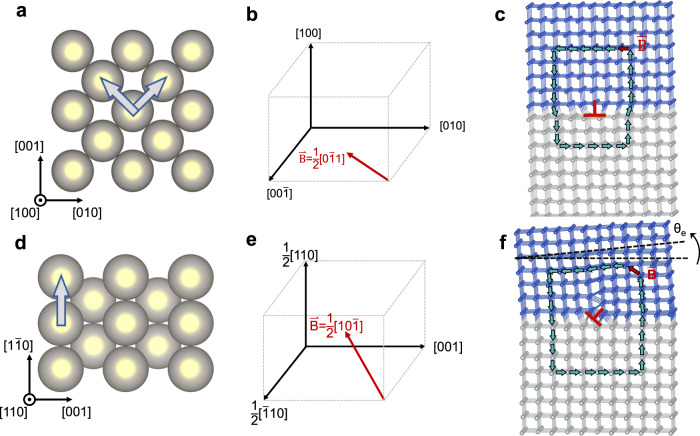
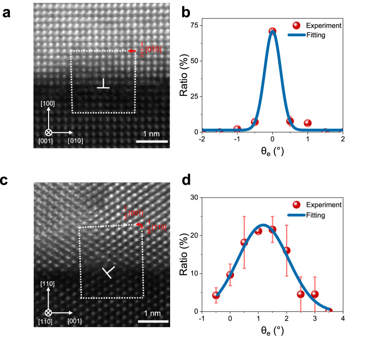
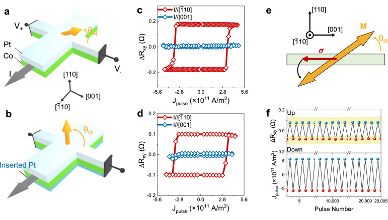
Current induced spin-orbit torque (SOT) holds great promise for next generation magnetic-memory technology. Field-free SOT switching of perpendicular magnetization requires the breaking of in-plane symmetry, which can be artificially introduced by external magnetic field, exchange coupling or device asymmetry. Recently it has been shown that the exploitation of inherent crystal symmetry offers a simple and potentially efficient route towards field-free switching. However, applying this approach to the benchmark SOT materials such as ferromagnets and heavy metals is challenging. Here, we present a strategy to break the in-plane symmetry of Pt/Co heterostructures by designing the orientation of Burgers vectors of dislocations. We show that the lattice of Pt/Co is tilted by about 1.2° when the Burgers vector has an out-of-plane component. Consequently, a tilted magnetic easy axis is induced and can be tuned from nearly in-plane to out-of-plane, enabling the field-free SOT switching of perpendicular magnetization components at room temperature with a relatively low current density (~1011 A/m2) and excellent stability (> 104 cycles). This strategy is expected to be applicable to engineer a wide range of symmetry-related functionalities for future electronic and magnetic devices.
© 2023. Springer Nature Limited.
Conflict of interest statement
The authors declare no competing interests.
Figures

Similar articles
-
Symmetry-dependent field-free switching of perpendicular magnetization.Nat Nanotechnol. 2021 Mar;16(3):277-282. doi: 10.1038/s41565-020-00826-8. Epub 2021 Jan 18. Nat Nanotechnol. 2021. PMID: 33462431
-
Full Electrical Manipulation of Perpendicular Magnetization in [111]-Orientated Pt/Co Heterostructure Enabled by Anisotropic Epitaxial Strain.Nano Lett. 2025 Apr 23;25(16):6670-6678. doi: 10.1021/acs.nanolett.5c00699. Epub 2025 Apr 15. Nano Lett. 2025. PMID: 40230257
-
Symmetry-breaking effects on spin-orbit torque switching in ferromagnetic semiconductors with perpendicular magnetic anisotropy.Sci Rep. 2025 Jul 7;15(1):24196. doi: 10.1038/s41598-025-09666-9. Sci Rep. 2025. PMID: 40624132 Free PMC article.
-
Switching of Perpendicular Magnetization by Spin-Orbit Torque.Adv Mater. 2023 Nov;35(48):e2300853. doi: 10.1002/adma.202300853. Epub 2023 Oct 25. Adv Mater. 2023. PMID: 37004142 Review.
-
Current-Induced Spin-Orbit Torques for Spintronic Applications.Adv Mater. 2020 Sep;32(35):e1907148. doi: 10.1002/adma.201907148. Epub 2020 Mar 6. Adv Mater. 2020. PMID: 32141681 Review.
Cited by
-
Highly efficient field-free switching of perpendicular yttrium iron garnet with collinear spin current.Nat Commun. 2024 Apr 13;15(1):3201. doi: 10.1038/s41467-024-47577-x. Nat Commun. 2024. PMID: 38615046 Free PMC article.
References
-
- Manchon A, et al. Current-induced spin-orbit torques in ferromagnetic and antiferromagnetic systems. Rev. Mod. Phys. 2019;91:035004. doi: 10.1103/RevModPhys.91.035004. - DOI
Grants and funding
- 51788104/National Natural Science Foundation of China (National Science Foundation of China)
- 52271181/National Natural Science Foundation of China (National Science Foundation of China)
- 51831005/National Natural Science Foundation of China (National Science Foundation of China)
- 52002204/National Natural Science Foundation of China (National Science Foundation of China)
- 92163113/National Natural Science Foundation of China (National Science Foundation of China)
LinkOut - more resources
Full Text Sources
