Review
. 2023 Aug 30;11(10):359.
doi: 10.21037/atm-22-3078. Epub 2023 Jan 9.

Robotic bronchoscopy in diagnosing lung cancer-the evidence, tips and tricks: a clinical practice review

Affiliations
Review

Robotic bronchoscopy in diagnosing lung cancer-the evidence, tips and tricks: a clinical practice review

Elliot Ho et al. Ann Transl Med. .

Abstract

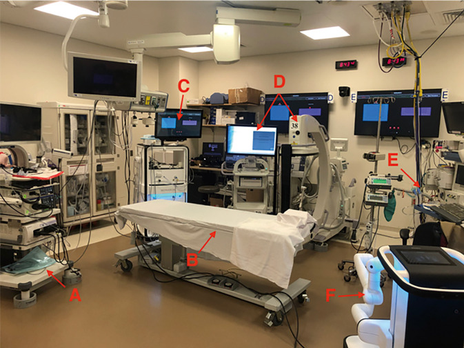
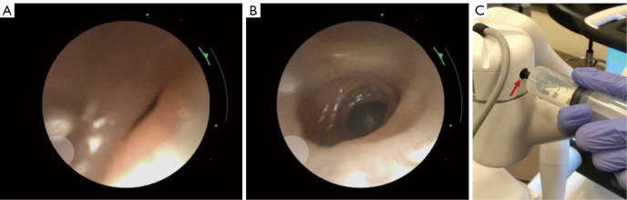
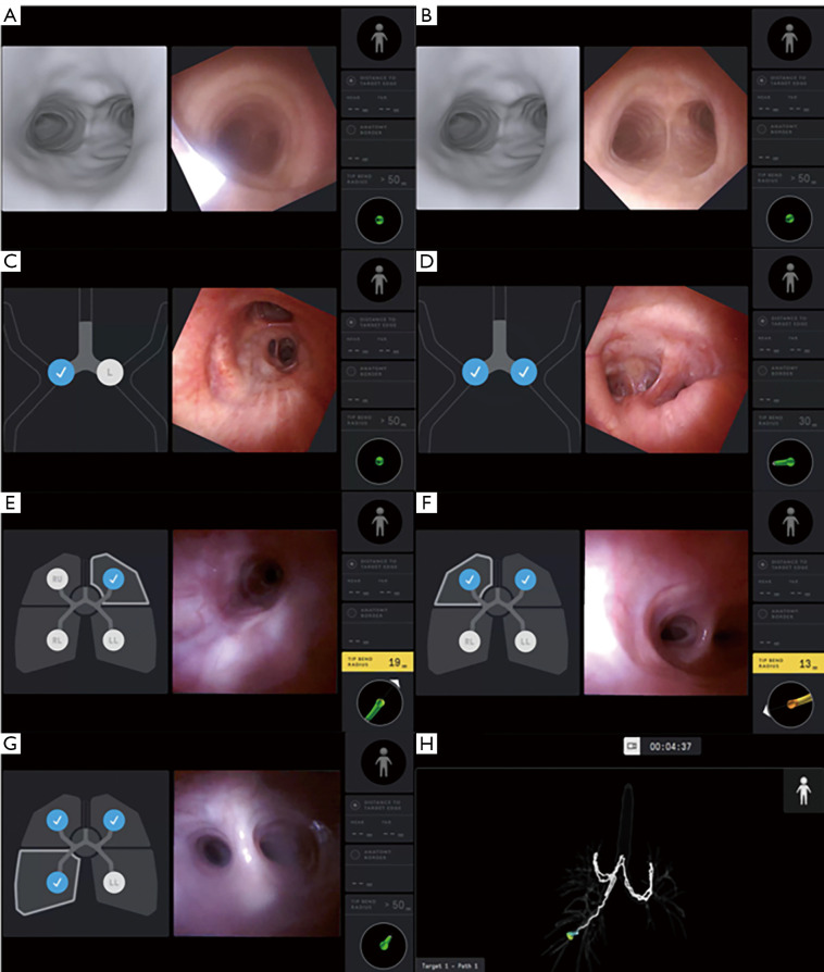
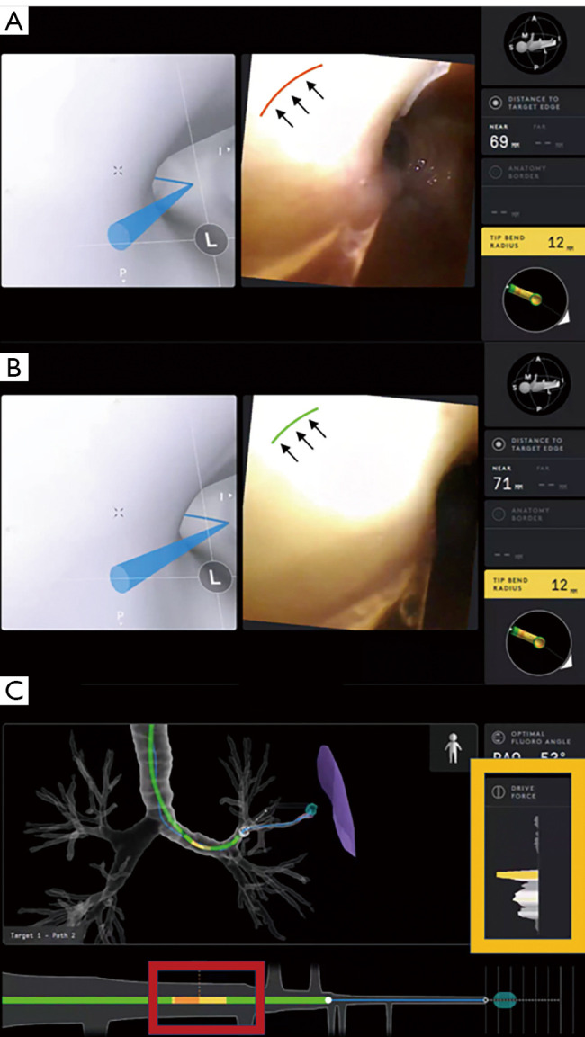
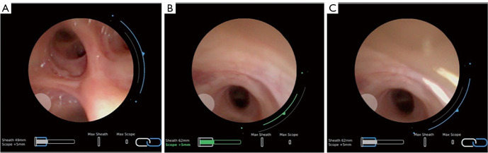
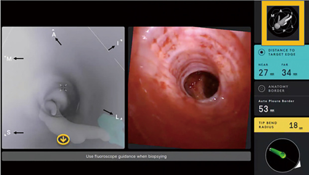
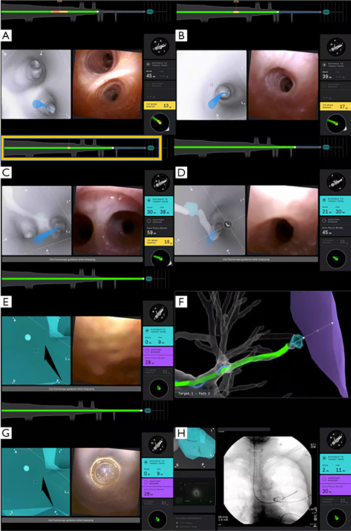
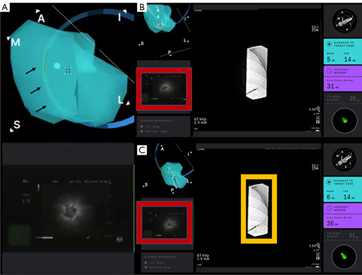
The development of robotic-assisted bronchoscopy has empowered bronchoscopists to access the periphery of the lung with more confidence and promising accuracy. This is due in large to the superior maneuverability, further reach, and stability of these technologies. Despite the advantages of robotic bronchoscopy, there are some drawbacks to using these technologies, such as the loss of tactile feedback, the need to overcome computed tomography (CT)-to-body divergence, and the potential for overreliance on the navigation software. There are currently two robotic bronchoscopy platforms on the US market, the MonarchTM Platform by Auris Health© (Redwood City, CA, USA) and the IonTM endoluminal robotic bronchoscopy platform by Intuitive Surgical© (Sunnyvale, CA, USA). In this clinical practice review, we highlight the evidence and strategies for successful clinical use of both robotic bronchoscopy platforms for pulmonary lesion sampling. Specifically, we will review pre-procedural considerations, such as procedural mapping, room set-up and anesthesia considerations. We will also review the technical aspects of using the robotic bronchoscopy platforms, such as how to compensate for the loss of tactile feedback, optimize visualization, use of ancillary technology to accommodate for CT-to-body divergence, employ best practices for sampling techniques, and utilize information from rapid on-site evaluation (ROSE) to aid in improving diagnostic yield.

Keywords: Robotic bronchoscopy; lung cancer; navigational bronchoscopy; pulmonary nodules.


Conflict of interest statement

Conflicts of Interest: All authors have completed the ICMJE uniform disclosure form (available at https://atm.amegroups.com/article/view/10.21037/atm-22-3078/coif). The series “Lung Cancer Management—The Next Decade” was commissioned by the editorial office without any funding or sponsorship. EH receives consulting fees from Intuitive, Olympus, and Biodesix. SM receives consulting fees from Olympus, Boston Scientific, Pinnacle Biologics, Johnson and Johnson, ERBE, Biodesix and Cook Inc. for developing and delivering educational events. The authors have no other conflicts of interest to declare.

Figures

Figure 1
Figure 1
Pre-procedural CT Chest showing a right upper lobe cavitary lesion is used for pathway mapping (A). Review of the CT Chest shows that to arrive at the target lesion, the bronchoscope must navigate via the right main bronchus (red arrow), then the anterior segment (yellow arrow), then take a posterior turn (green arrow), then take one more anterior turn (blue arrow), and lastly potentially another anterior turn (purple arrow) (B). It is important to ensure that there is appropriate understanding of the lesion to airway relationship and writing down this plan prior to the procedure could be useful in cases of CT-to-body divergence. CT, computed tomography.
Figure 2
Figure 2
Example of planning a target in the Monarch system software. A target is chosen (A) and marked (B). The software will draw a pathway automatically along segmented airways which in this example is stopping proximal of target itself (C). A pathway can be manually drawn (D) and traced back, in this example along a blood vessel (E,F) until contacting a segmented airway at which point the software will complete the pathway (G). The new pathway is shown leading into the target (H). Generated pathways have to be without sharp angulation, especially in the mid and outer third of the lung (see image H bottom right panel). That ensures that the pathway follows normal structures (airway or vessels) and is not artificially created through the lung parenchyma.
Figure 3
Figure 3
A mapped pathway (blue line) extending to the virtual target is seen on a computer-generated airway tree. Although in close proximity to the virtual target, the mapped pathway (blue line) exits the airway at a very sharp angle as indicated by the high exit angle (yellow box). This is not consistent with subsegmental airway branching (A). A different pathway is mapped towards the virtual target, this time exiting the airway at a more gradual angle as indicated by the low exit angle (yellow box) (B).
Figure 4
Figure 4
Vessel sign planning in the absence of bronchus sign. Pre-procedural planning CT chest showing the vessel leading to a nodule (yellow arrows) (A). A pathway to the target lesion is created by manually adding points along the vessel from the target lesion to the central airway. This is demonstrated by the yellow pathway from the lesion connecting to the central airway (B). CT, computed tomography.
Figure 5
Figure 5
Example of room set up for MonarchTM system. Pictured are bronchoscopy tower (A), fluoroscopy compatible bed (B), Monarch tower (C), C-arm and fluoroscopy tower (D), anesthesia machine (E), and Monarch robotic bronchoscope driver (F). Not pictured are stations for specimen handling, cytopathology/ROSE, and nursing. ROSE, rapid on-site evaluation.
Figure 6
Figure 6
Decreased elastic recoil in COPD; airway collapsibility encountered (A) proximal to the target. Improvement in airway patency (B) is obtained by insufflating air through a 60-mL syringe (C). The proximal valve of the robotic bronchoscope is indicated by the red arrow. COPD, chronic obstructive pulmonary disease.
Figure 7
Figure 7
Registration process with the Ion robotic bronchoscopy platform using partial registration in a patient with left lower lobe resection. The robotic catheter and vision probe enter the endotracheal tube into the trachea above the main carina (A). The live image (right panel) is rotated counter-clockwise to align with the virtual image (left panel) (B). The robotic catheter is advanced into the right main bronchus (C), the left main bronchus (D), the left upper lobe (E), the right upper lobe (F), and the right lower lobe (G). A schematic of all the data points gathered during the registration process is seen on a virtual tracheobronchial tree overlay (H).
Figure 8
Figure 8
Endoluminal view with the Ion robotic bronchoscopy platform during navigation. The amount and direction of pressure applied by the robotic catheter onto the surrounding airway wall is indicated by the red curved line at the 11 o’clock position (black arrows) (A). The pressure is lessened by moving the robotic catheter away in the opposite direction, as indicated by the green curved line at the 11 o’clock position (black arrows) (B). The amount of pressure applied onto the anterior aspect of the robotic catheter is indicated by the drive force (yellow box), and the amount of tension along different points of the robotic catheter is indicated by different colors (red box) (C).
Figure 9
Figure 9
Leapfrog technique to navigate to apical segment of RUL. Sheath is in the RUL but unable to advance it in the RB1 (apical segment) despite maximum articulation; see blue line expanding to the two dots (A). After decoupling, the scope is advanced in RB1 (B). Then the scope and the sheath are recoupled, and the sheath is now in the RB1 segment (C). Navigation is then continued in the scope mode. RUL, right upper lobe.
Figure 10
Figure 10
The endoluminal compass is a useful feature on the Ion robotic bronchoscopy platform that helps correlate the position of the robotic catheter in relation to the patient’s airway anatomy and target lesion. Letters (black arrows) are seen on the virtual image (left panel), which indicate the respective anatomic positions (A = anterior, I = inferior, L = lateral, P = posterior, S = superior, M = medial). The positional relationship between the robotic catheter and the patient’s airway anatomy is also depicted on a 3D figurine (yellow box). 3D, three-dimensional.
Figure 11
Figure 11
Example of navigation with the IonTM system. The live image (right panel) correlates with the virtual image (left panel). The blue line indicates the mapped pathway leading to the target lesion (A). The robotic catheter is advanced distally, following the blue line (B). As the robotic catheter is advanced distally, the operator should make sure that the live and virtual images match. Of note, the schematic above the live and virtual images (yellow box) indicates whether the robotic catheter is following or deviating from the planned pathway (C). The virtual target comes into view as the robotic catheter is advanced further following the mapped pathway (D). The robotic catheter is seen adjacent to the target lesion (E). Virtual tracheobronchial tree overlay demonstrates successful navigation to the target lesion (F). The vision probe is retracted slightly within the robotic catheter, showing that it is tented well against the airway mucosa (G). The vision probe is removed from the robotic catheter and replaced with the r-EBUS probe. An eccentric image on r-EBUS is acquired (H). r-EBUS, radial endobronchial ultrasound.
Figure 12
Figure 12
The articulation guide (black arrows) can be turned on to systemically guide the placement of the r-EBUS probe on different surfaces of the airway wall as the operator evaluates for the strongest r-EBUS signal (A). An eccentric r-EBUS view is obtained when the r-EBUS probe is advanced towards the lesion (red box) (B). Adjustments are made to the robotic catheter, by moving it anteriorly and superiorly as indicated by the endoluminal compass. A concentric view (red box) is obtained when r-EBUS probe is advanced towards the target lesion (C). Of note, the fluoroscopic projection is collimated to reduce the amount of radiation to the patient and procedure staff (yellow box). A, anterior; S, superior; M, medial; r-EBUS, radial endobronchial ultrasound.
Figure 13
Figure 13
Example of stylet pull-back technique of needle aspiration. Needle system is advanced through working channel (A) until in position. Needle itself is advanced out of sheath into target with stylet slightly withdrawn (B). Stylet is advance to clear needle channel (C). Stylet is withdrawn several inches to establish negative pressure (D). Needle system is agitated forward and backward within target with stylet left partially withdrawn (E). Once sampling is completed, needle is withdrawn into system without manipulating stylet (F). Needle system is then withdrawn from working channel and specimen is deployed on slides for rapid on-site cytology evaluation.
Figure 14
Figure 14
Airway bleeding is seen under continuous visualization on the MonarchTM Platform after biopsy of target lesion with grasping forceps (A). Since the sheath is wedged in the most distal segmental or sub-segmental airway possible, the blood will be drained through the scope into the suction tubing instead of spilling into the other segments causing hypoxemia (B). Iced saline is gently instilled via the working channel of the robotic bronchoscope to facilitate hemostasis (C). Hemostasis is achieved as no further bleeding is visualized on the robotic bronchoscope (D).

Similar articles

Cited by

References

    1. Wahidi MM, Govert JA, Goudar RK, et al. Evidence for the treatment of patients with pulmonary nodules: when is it lung cancer?: ACCP evidence-based clinical practice guidelines (2nd edition). Chest 2007;132:94S-107S. - PubMed
    1. Sachdeva M, Ronaghi R, Mills PK, et al. Complications and Yield of Computed Tomography-Guided Transthoracic Core Needle Biopsy of Lung Nodules at a High-Volume Academic Center in an Endemic Coccidioidomycosis Area. Lung 2016;194:379-85. 10.1007/s00408-016-9866-3 - DOI - PubMed
    1. Folch EE, Labarca G, Ospina-Delgado D, et al. Sensitivity and Safety of Electromagnetic Navigation Bronchoscopy for Lung Cancer Diagnosis: Systematic Review and Meta-analysis. Chest 2020;158:1753-69. 10.1016/j.chest.2020.05.534 - DOI - PubMed
    1. Chen AC, Pastis NJ, Jr, Mahajan AK, et al. Robotic Bronchoscopy for Peripheral Pulmonary Lesions: A Multicenter Pilot and Feasibility Study (BENEFIT). Chest 2021;159:845-52. 10.1016/j.chest.2020.08.2047 - DOI - PMC - PubMed
    1. Chaddha U, Kovacs SP, Manley C, et al. Robot-assisted bronchoscopy for pulmonary lesion diagnosis: results from the initial multicenter experience. BMC Pulm Med 2019;19:243. 10.1186/s12890-019-1010-8 - DOI - PMC - PubMed