. 2023 Aug 25;23(17):7421.
doi: 10.3390/s23177421.

Smooth Autonomous Patrolling for a Differential-Drive Mobile Robot in Dynamic Environments

Affiliations

Smooth Autonomous Patrolling for a Differential-Drive Mobile Robot in Dynamic Environments

Ana Šelek et al. Sensors (Basel). .

Abstract

Today, mobile robots have a wide range of real-world applications where they can replace or assist humans in many tasks, such as search and rescue, surveillance, patrolling, inspection, environmental monitoring, etc. These tasks usually require a robot to navigate through a dynamic environment with smooth, efficient, and safe motion. In this paper, we propose an online smooth-motion-planning method that generates a smooth, collision-free patrolling trajectory based on clothoid curves. Moreover, the proposed method combines global and local planning methods, which are suitable for changing large environments and enabling efficient path replanning with an arbitrary robot orientation. We propose a method for planning a smoothed path based on the golden ratio wherein a robot's orientation is aligned with a new path that avoids unknown obstacles. The simulation results show that the proposed algorithm reduces the patrolling execution time, path length, and deviation of the tracked trajectory from the patrolling route compared to the original patrolling method without smoothing. Furthermore, the proposed algorithm is suitable for real-time operation due to its computational simplicity, and its performance was validated through the results of an experiment employing a differential-drive mobile robot.

Keywords: mobile robot; motion planning; path smoothing; patrolling.


Conflict of interest statement

The authors declare no conflict of interest.

Figures

Figure 1
Figure 1
A theoretical framework for robot motion planning.
Figure 2
Figure 2
Control architecture of a differential-drive mobile robot.
Figure 3
Figure 3
The pipeline of the smooth patrolling scheme.
Figure 4
Figure 4
Two robots’ positions along with real obstacles (green dots), the patrolling route (blue line), the smoothed patrolling path (red line), and the tracked trajectory (green line).
Figure 5
Figure 5
Orientation alignment is based on a golden ratio, where angle γ is the divergence between the robot’s current orientation φc and the direction of the first segment β on the replanned TWD* path.
Figure 6
Figure 6
Clothoid with a length of 10 m interpolated via circular interpolation with the sampling interval Δs = 0.1 and interpolation error for different values of the sampling interval Δs. (a) Clothoid interpolated via circular interpolation. (b) Interpolation error e for different values of sampling interval Δs in the lookup table.
Figure 7
Figure 7
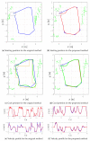
The comparison of the patrolling route (blue line) with the original patrolling method and the proposed smooth method, smoothed patrolling path (red line), the tracked trajectory (green line), the reference velocity profile (blue line), and the actual velocity profile (red line). (a) Patrol carried out using the original patrolling method. (b) Patrol carried out using the proposed smooth method. (c) Velocity profile yielded when using the original patrolling method. (d) Velocity profile yielded when using the proposed smooth method.
Figure 8
Figure 8
The curvature profile of the smooth patrolling path from Figure 7b.
Figure 9
Figure 9
The smoothed path in a static environment for the proposed method and other state-of-the-art smoothing methods.
Figure 10
Figure 10
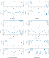
Curvature profiles and tangent angle change on a smooth path in a static environment with the proposed method and other state-of-the-art smoothing methods.
Figure 11
Figure 11
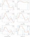
Velocity profiles on a smooth path in a static environment for the proposed method and other state-of-the-art smoothing methods.
Figure 12
Figure 12
The patrolling route (blue line) during the execution of replanning, smoothed patrolling path (red line), the tracked trajectory (green line), the reference velocity profile (blue line), and the actual velocity profile (red line).
Figure 13
Figure 13
The step-by-step local path-planning scheme in a dynamic environment presenting the travel trajectories of robot1 and robot2 (cyan dashed lines) toward goal1 and goal2, respectively: the STWD* (green line), APF (red line), DWA (magenta line), and MPC (blue line) travel trajectories of robot0 from start to goal0.
Figure 14
Figure 14
Velocity profiles of compared local path-planning algorithms executed in a dynamic environment: the STWD* (green line), APF (red line), DWA (magenta line), and MPC algorithms (blue line).
Figure 15
Figure 15
Experimental setup for smooth autonomous patrolling using the Husky mobile robot.
Figure 16
Figure 16
A comparison of patrolling route (blue line) traveled using the original and the proposed smooth methods: D* path (yellow line), smoothed patrolling path (red line), the tracked trajectory (green line), the reference velocity profile (blue line), and the actual velocity profile (red line).
Figure 17
Figure 17
The step-by-step patrolling task executed in a static environment where the real obstacles are presented as extracted 2D laser range data from the Velodyne point cloud data (green dots), the patrolling path (blue line), the smooth patrolling path (red line), replanned TWD* path (black line), and tracked trajectory from start to goal (green line).
Figure 18
Figure 18
Velocity profile for the proposed method during the execution of the patrolling task in a static environment, presenting the reference velocity profile (blue line) and the actual velocity profile (red line).
Figure 19
Figure 19
The execution of the step-by-step patrolling task in a dynamic environment, where the real obstacles are presented as extracted 2D laser range data from the Velodyne point cloud data (green dots), along with the patrolling path (blue line), the smooth patrolling path (red line), replanned TWD* path (black line), tracked trajectory from start to goal (green line), and the dynamic obstacle trajectory (magenta line).
Figure 20
Figure 20
Velocity profile for the proposed method during the execution of the patrolling task in a dynamic environment, presenting the reference velocity profile (blue line) and the actual velocity profile (red line).

References

    1. Farooq M.U., Eizad A., Bae H.K. Power solutions for autonomous mobile robots: A survey. Robot. Auton. Syst. 2023;159:104285. doi: 10.1016/j.robot.2022.104285. - DOI
    1. Azpúrua H., Saboia M., Freitas G.M., Clark L., Agha-mohammadi A.A., Pessin G., Campos M.F., Macharet D.G. A Survey on the autonomous exploration of confined subterranean spaces: Perspectives from real-word and industrial robotic deployments. Robot. Auton. Syst. 2023;160:104304. doi: 10.1016/j.robot.2022.104304. - DOI
    1. Couillard M., Fawcett J., Davison M. Optimizing Constrained Search Patterns for Remote Mine-Hunting Vehicles. IEEE J. Ocean. Eng. 2012;37:75–84. doi: 10.1109/JOE.2011.2173833. - DOI
    1. Abouaf J. Trial by fire: Teleoperated robot targets Chernobyl. IEEE Comput. Graph. Appl. 1998;18:10–14. doi: 10.1109/38.689654. - DOI
    1. Hoshino S., Ishiwata T., Ueda R. Optimal patrolling methodology of mobile robot for unknown visitors. Adv. Robot. 2016;30:1072–1085. doi: 10.1080/01691864.2016.1192064. - DOI

LinkOut - more resources