. 2023 Apr 6;8(7):2201778.
doi: 10.1002/admt.202201778. Epub 2023 Feb 3.

Building Blood Vessel Chips with Enhanced Physiological Relevance

Affiliations

Building Blood Vessel Chips with Enhanced Physiological Relevance

Xuan Mu et al. Adv Mater Technol. .

Abstract

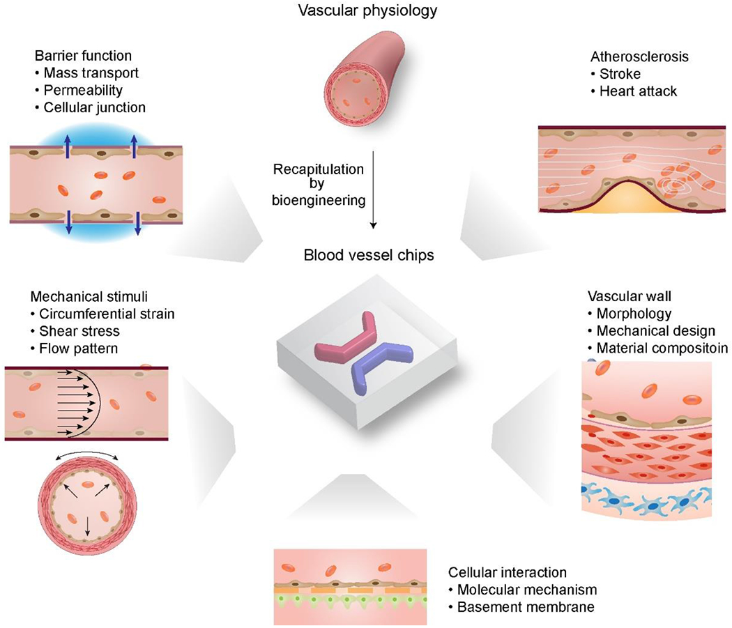
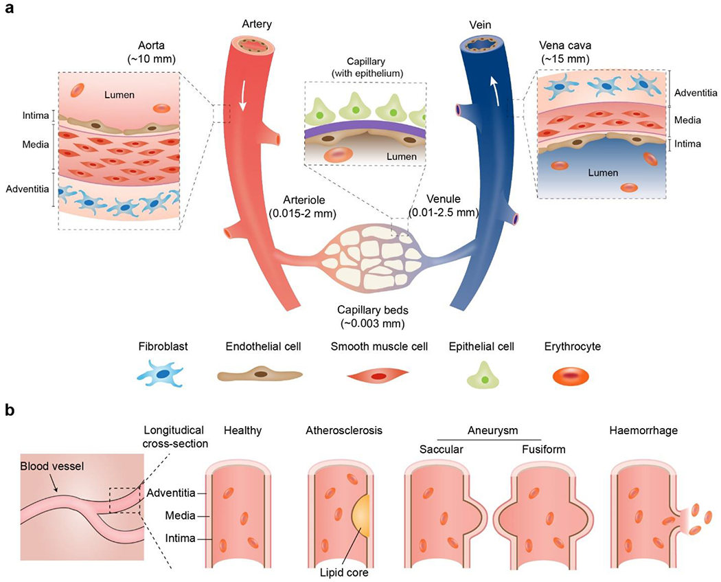
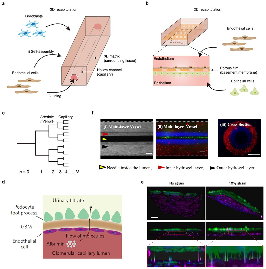
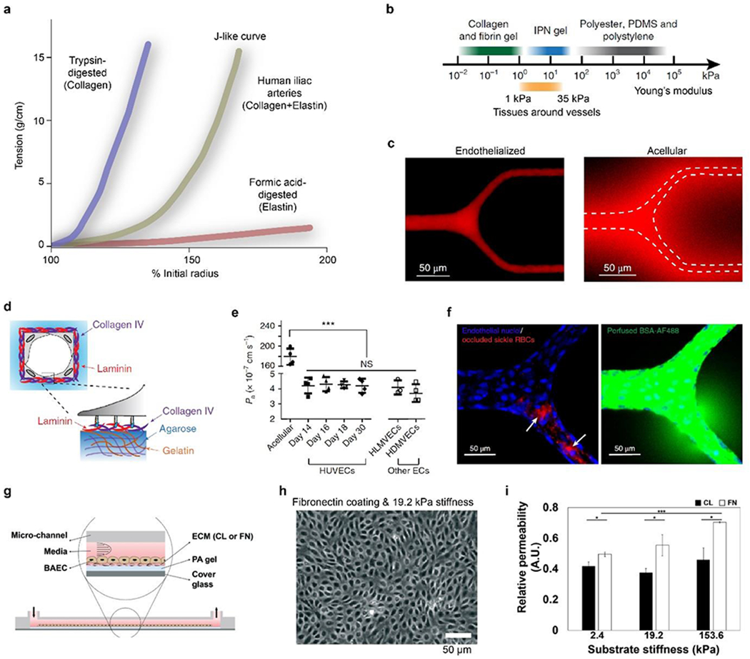
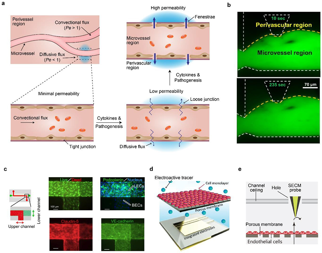
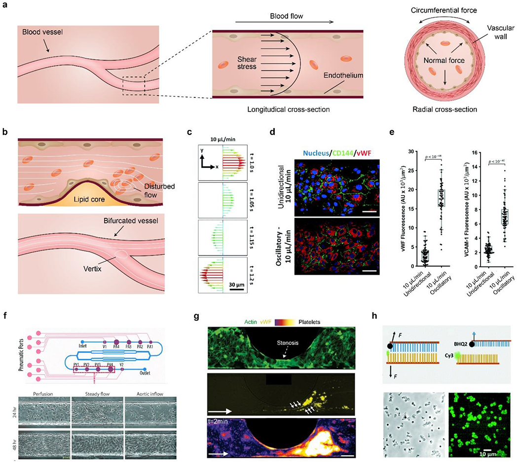
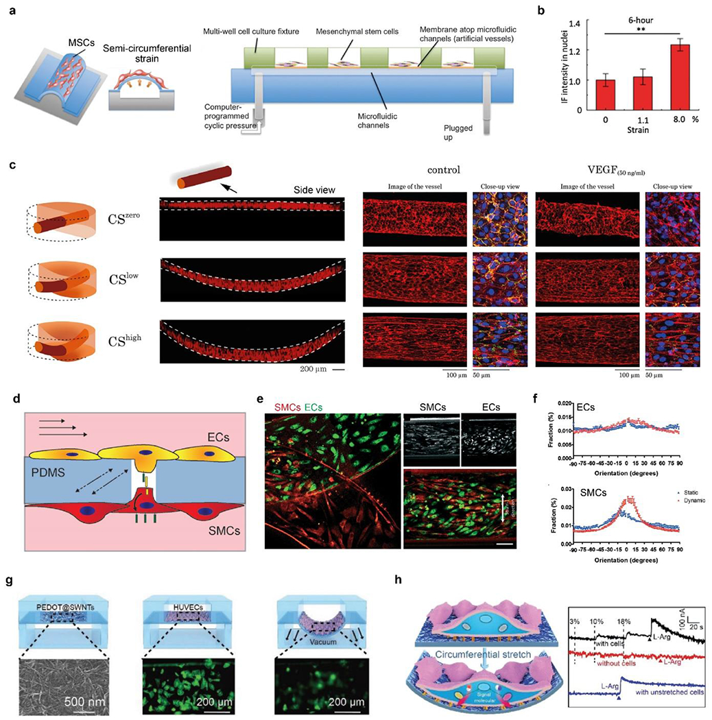
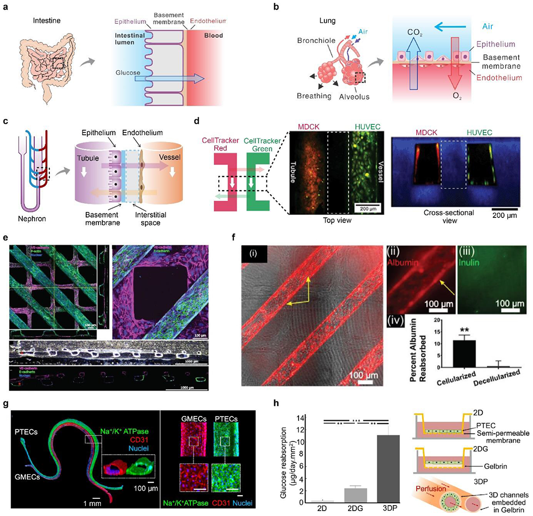
Blood vessel chips are bioengineered microdevices, consisting of biomaterials, human cells, and microstructures, which recapitulate essential vascular structure and physiology and allow a well-controlled microenvironment and spatial-temporal readouts. Blood vessel chips afford promising opportunities to understand molecular and cellular mechanisms underlying a range of vascular diseases. The physiological relevance is key to these blood vessel chips that rely on bioinspired strategies and bioengineering approaches to translate vascular physiology into artificial units. Here, we discuss several critical aspects of vascular physiology, including morphology, material composition, mechanical properties, flow dynamics, and mass transport, which provide essential guidelines and a valuable source of bioinspiration for the rational design of blood vessel chips. We also review state-of-art blood vessel chips that exhibit important physiological features of the vessel and reveal crucial insights into the biological processes and disease pathogenesis, including rare diseases, with notable implications for drug screening and clinical trials. We envision that the advances in biomaterials, biofabrication, and stem cells improve the physiological relevance of blood vessel chips, which, along with the close collaborations between clinicians and bioengineers, enable their widespread utility.

Keywords: COVID-19; angiogenesis; disease modeling; drug screening; hemodynamics; permeability; rare disease.


Conflict of interest statement

Conflicts of Interest YSZ sits on the scientific advisory board of Allevi by 3D Systems and Xellar, which however, did not participate in or bias the work.

Figures

Figure 1.
Figure 1.
Overview of blood vessel chips recapitulating sophisticated vascular (patho)physiology, including morphology, mechanical properties and stimuli, mass transport, and compositions, laying a foundation for various biomedical research.
Figure 2.
Figure 2.
a) Schematic anatomy of blood vessels at hierarchical length scales. The vascular walls of the aorta and vena cava comprise three concentric layers termed the intima, media, and adventitia, respectively. The capillary wall usually contains a single layer of the intima. In some tissues, such as the lung alveoli and renal nephron, blood capillary is often accompanied by the epithelium. b) Schematic longitudinal cross-sections of healthy and pathological vascular walls, such as aneurysms (saccular and fusiform), atherosclerosis, and hemorrhage.
Figure 3.
Figure 3.
a) Schematic of 3D blood vessel chips. Microchannels are constructed within a 3D matrix. ECs and other cell types, e.g., fibroblasts, are seeded into the microchannel or the hydrogel matrix. b) Schematic of 2D blood vessel chips. Microchannels are separated by a porous membrane. ECs and other types of cells, often epithelial ones, are seeded onto the two sides of the membrane, respectively. c) Schematic of a bifurcated, hierarchical vascular network, where n is the hierarchical number. Reproduced with permission.[109] Copyright 2006, Royal Society of Chemistry. d) Schematic of glomerular cross-section reconstructed in tissue chips. EC-lined capillary is separated from the epithelial cell (podocyte)-lined urinary space by a glomerular basement membrane (GBM). Large molecules such as albumin are retained in capillaries, while small molecules like inulin are filtered into the urine. In the tissue chip, ECs and hiPSC-induced podocytes are cultured on the two sides of a porous elastic PDMS membrane, which mimic the urinary and capillary compartments and the GBM, respectively. The cells can be stretched by manipulating vacuum inside channels. e) 3D reconstruction of the on-chip interface between podocytes (green) and ECs (magenta). 10% cyclic strain enhanced the extension of podocytes through the porous membrane and insertion into the biomimicked glomerular endothelium. Scale bar, 100 μm. d and e) Reproduced with permission.[163] Copyright 2017, Springer Nature. f) Multi-layered vessel-like structure. (i) Top view, brightfield. (ii) Top view, fluorescence. Red and blue fluorescence indicate two layers of the vessel, respectively. Green fluorescence indicates flowing beads in the lumen. (iii) Cross-sectional view, fluorescence. Scale bars, 200 μm. Reproduced with permission.[165] Copyright 2015, Springer Nature.
Figure 4.
Figure 4.
a) Composite components of elastin and collagen contribute to the J-like tension-length (stress-strain) behavior of human iliac arteries. Reproduced with permission.[168] Copyright 1999, Journal of Experimental Biology. b) Stiffness of IPN hydrogel covers a range between common soft hydrogels and stiff polymeric materials, agreeing well with physiological tissues surrounding vessels. c) ECs cultured in a branched IPH hydrogel channel form a tight monolayer and are impermeable to red-fluorescent Alexa Fluor 549-labeled bovine serum albumin after 15-min perfusion, compared to an acellular hydrogel channel with notable diffusion. White dash line indicates the boundary of microchannels. d) Schematic of the deposition of basement membrane components, such as laminin and collagen IV. e) Physiology-relevant permeability using HUVECs and other ECs can last up to 30 days in IPN microchannels. f) 3D confocal images of the endothelialized IPN microchannels perfused with sickle RBCs and Alexa 488-labeled bovine serum albumin. Sickle RBC occlusions, indicated by white arrows, lead to the local increase in permeability. b-f) Reproduced with permission.[146] Copyright 2018, Springer Nature. g) Schematic of a vessel mimicking microchannel constituted with PA hydrogels and ECM coatings. h) Phase-contrast image of an ECs monolayer on fibronectin (FN)-coated PA hydrogels with 19.2-kPa stiffness after one hour of shear stress. i) ECM coating influences cellular responses to substrate stiffness. Permeability of FN coating is higher than collagen (CL) coating and depends on stiffness. g-i) Reproduced with permission.[181] Copyright 2019, Royal Society of Chemistry.
Figure 5.
Figure 5.. Permeability of vessels and blood vessel chips.
a) Schematic of vascular permeability related to endothelial junctions. Assumed flux and Pe number are also shown. b) On-chip measurement of vascular permeability by fluorescence diffusion from microvessel region to perivascular region at 10 and 253 seconds. Yellow dash line indicates boundaries of vessels. White dash line indicates on-chip microstructures. Reproduced with permission.[190] Copyright 2014, Elsevier. c) On-chip co-culture of blood vascular ECs (BECs, upper channel) and lymphatic ECs (LECs, lower channel) for investigating venom-indued hemorrhage and increased permeability. Both cells are confluent and express tight-junction proteins. Reproduced with permission.[182] Copyright 2015, Creative Commons Attribution License. d) Schematic of on-chip planar electrodes to detect electroactive tracers passing through an EC monolayer and a membrane. Reproduced with permission.[194] Copyright 2019, Royal Society of Chemistry. e) Schematic of an SECM probe for detecting permeability of EC monolayer. Reproduced with permission.[194] Copyright 2021, John Wiley and Sons.
Figure 6.
Figure 6.
a) Schematic diagram of mechanical forces on vessels, including shear, normal and circumferential ones. b) Disturbed blood flow and vortices due to bifurcation and accumulated lipid-rich plaque. Platelets may aggregate at a post-stenosis site. c) Simulated velocity profile of an oscillatory flow at 10 μL/min and 0.3 Hz. d) Fluorescence images of ECs stained with the nucleus, cluster of differentiation (CD)-144, and vWF under unidirectional and oscillatory flows. Scale bar, 50 μm. e) Quantitative comparison of vWF and VCAM-1 under the two different flow conditions. c-e) Reproduced with permission.[180] Copyright 2021, Royal Society of Chemistry. f) Schematic of a vessel chip for generating a range of flow profiles. The frequency and magnitude of shear stress can be manipulated by on-chip pumping and valve size (P1-4, PV1-4). Primary valvular ECs exhibit different morphology and alignment under flow conditions. Scale bar, 50 μm. Reproduced with permission.[235] Copyright 2018, Royal Society of Chemistry. g) Platelet aggregation in a stenotic microfluidic channel lined with ECs. Dash arrow indicates the stenosis. Top, endothelial monolayer stained with F-actin (green); middle, vWF (yellow) expressed at post-stenotic sites, indicated by six small arrows; bottom, platelets, stained with DiOC6, are aggregated at the post-stenotic site after the whole blood perfusion. The platelet density increases as the color changes from black, purple, red, yellow to white. White arrow indicates the flow direction. Scale bar, 100 μm. Reproduced with permission.[180] h) Top, schematic of DNA-based integrin tension sensor. Black hole quencher 2 (BHQ2) quenches the fluorescence of the adjacent Cy3 probe. Upon removing the tope DNA chain by flow stress, the fluorescence of Cy3 becomes visible. Bottom, representative optical and force-mapping images (in green fluorescence) of platelets in the microfluidic channel. Reproduced with permission.[243] Copyright 2021, Royal Society of Chemistry.
Figure 7.
Figure 7.
a) Schematic of microfluidic chips with semi-circumferential deformation. b) quantitative comparison of the nucleus accumulation of β-catenin under circumferential strains. a-b) Reproduced with permission.[254] Copyright 2012, Oxford University Press. c) Schematic and fluorescence images (side view) of the 3D vessels under zero, low, and high circumferential strains (CS). CS increases cellular alignment and counteracts VEGF to stabilize vessels. F-actin (red), platelet endothelial cell adhesion molecule-1 (PECAM-1, green), and DAPI (blue). Reproduced with permission.[257] Copyright 2021, Creative Commons Attribution license. d) Schematic of ECs and SMCs cocultured on a porous PDMS membrane in a vessel chip and exposed to shear stress and circumferential strain. e) Fluorescence image of ECs and SMCs after 4-day of culturing under mechanical stimuli, i.e., dynamic culture. Scale bar, 100 μm. f) Quantitative analyses of cellular alignment under static and dynamic culturing conditions. d-f) Reproduced with permission.[258] Copyright 2018, Creative Commons Attribution license. g) Schematic of in situ, real-time monitoring of mechanical stimuli using a flexible electrochemical sensor. HUVECs (in green) become blurred when they stretched and were out of focus. H) Right, schematic of cellular mechanotransduction to release NO. Left, electrochemical curves of cells responding to 0%, 10%, and 18% strains, and L-arginine. G-h) Reproduced with permission.[262] Copyright 2019, John Wiley and Sons.
Figure 8.
Figure 8.. Intravascular mass transport and kidney reabsorption.
A) Schematic of intervascular mass transport in the intestine. b) Schematic of intervascular mass transport in the lung. C) Schematic of intervascular mass transport in the nephron. d) A biomimetic nephron constructed in a monolithic hydrogel vessel chip. Two channels, lined by Madin-Darby canine kidney cells (MDCKs) and HUVECs, represented the tubule and vessel, respectively. Two fluorescent dyes, CellTraker red and green, were perfused into one channel and allowed to diffuse into the other channel. White dash boxes indicate hydrogel located between two channels. Reproduced with permission.[42] Copyright 2013, Royal Society of Chemistry. e) Cellularized tubules (in purple) and vessels (in green) were constructed in collagen hydrogels, mechanically supported by polymer scaffolds. f) Albumin-reabsorption in the tubule, compared with inulin and decellularized devices. e-f) Reproduced with permission. [293] Copyright 2018, John Wiley and Sons. g) PTECs and glomerular microvascular ECs (GMECs) for confluent monolayers in hydrogel channels to mimic renal tubules and vessels. Scale bar, 100 μm. h) Schematic and quantitative glucose-reabsorption in the 3D hydrogel channel, compared to two 2D models. G-h) Reproduced with permission.[137] Copyright 2019, Creative Commons Attribution license.
Figure 9.
Figure 9.
a) Schematic of HGPS pathogenesis. Mutations of the LMNA gene, such as C1824T, lead to aberrant mRNA splicing and permanent farnesylation of lamin A, i.e., progerin, that accumulates at the nuclear periphery. Reproduced with permission.[299] Copyright 2014, Elsevier. b) Schematic of blood vessel chips to investigate HGPS hiPSC-SMCs under mechanical stimuli. c) Both healthy and HGPS hiPSC-SMCs exhibit improved alignment under 16% strain. #, P < 0.0001. Red arrow indicates stretching direction. Scale bar, 50 μm. d) 16% mechanical strain leads to DNA double-strand breaks (H2A.X immunostaining) and a slight increase of senescence (β-galactosidase-induced fluorescence) of HGPS hiPSC-SMC. b-d) Reproduced with permission.[246] Copyright 2017, John Wiley and Sons.
Figure 10.
Figure 10.
a) Schematic, fluorescence image and heat map of a vessel chip, consisting of human ECs (red) and ECM (green). Flow-induced shear stress, around 5 dyn/cm2, led to low vascular permeability, compared with static conditions. b) Schematic of NOTCH1 mechanosensory complex, encompassing LAR and TRIO, for stabilizing cellular junctions via the activation of RAC1. a-b) Reproduced with permission.[193] Copyright 2017, Springer Nature. c) Fluorescence images and western blots indicating the reduced expression of cluster of CD31, and the increased level of vimentin and α-SMA upon exposure to oscillatory flow. d) Schematic of the underlying mechanism of interactions between ECs and SMCs, involving paracrine communication and RANTES activation. c-d) Reproduced with permission.[335] Copyright 2021, Creative Commons Attribution NonCommercial License. e) Schematic of constructing intima-media interface using varying channel heights and CBV effect. f) Phase-contrast images of migrated SMC into the subendothelial layer in response to the treatment of inflammatory cytokines, including IL-1β and TNF-α. e-f) Reproduced with permission.[336] Copyright 2021, Royal Society of Chemistry.

Similar articles

Cited by

References

    1. Zhang B, Korolj A, Lai BFL, Radisic M, Nat. Rev. Mater 2018, 3, 257.
    1. Bhatia SN, Ingber DE, Nat. Biotechnol 2014, 32, 760. - PubMed
    1. Zhang YS, Aleman J, Shin SR, Kilic T, Kim D, Shaegh SAM, Massa S, Riahi R, Chae S, Hu N, Proc. Natl. Acad. Sci 2017, 114, E2293. - PMC - PubMed
    1. Ren K, Zhou J, Wu H, Accounts of Chemical Research 2013, 46, 2396. - PubMed
    1. Ren K, Chen Y, Wu H, Current Opinion in Biotechnology 2014, 25, 78. - PubMed

LinkOut - more resources