

Fabrication of a multifaceted mapping mirror using two-photon polymerization for a snapshot image mapping spectrometer
- PMID: 37706858
- PMCID: PMC11088238
- DOI: 10.1364/AO.495466
Fabrication of a multifaceted mapping mirror using two-photon polymerization for a snapshot image mapping spectrometer
Abstract
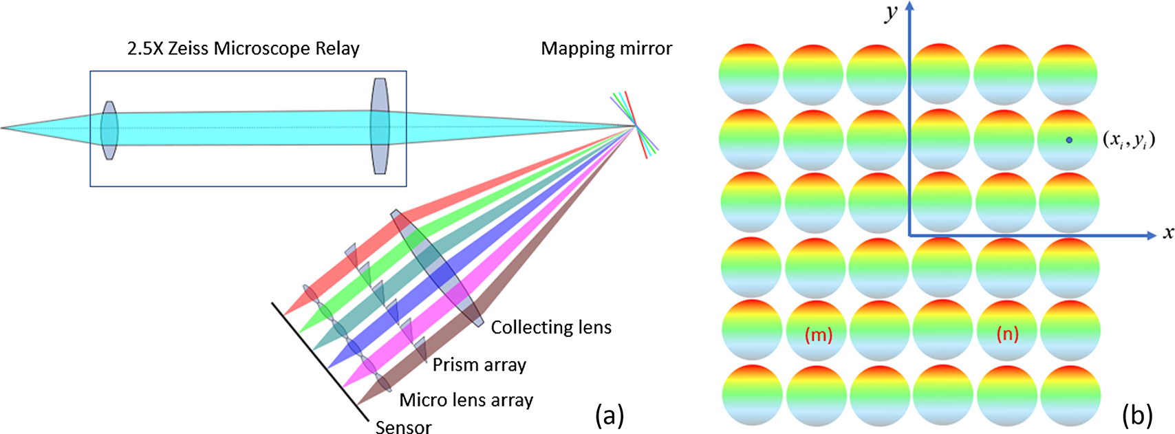
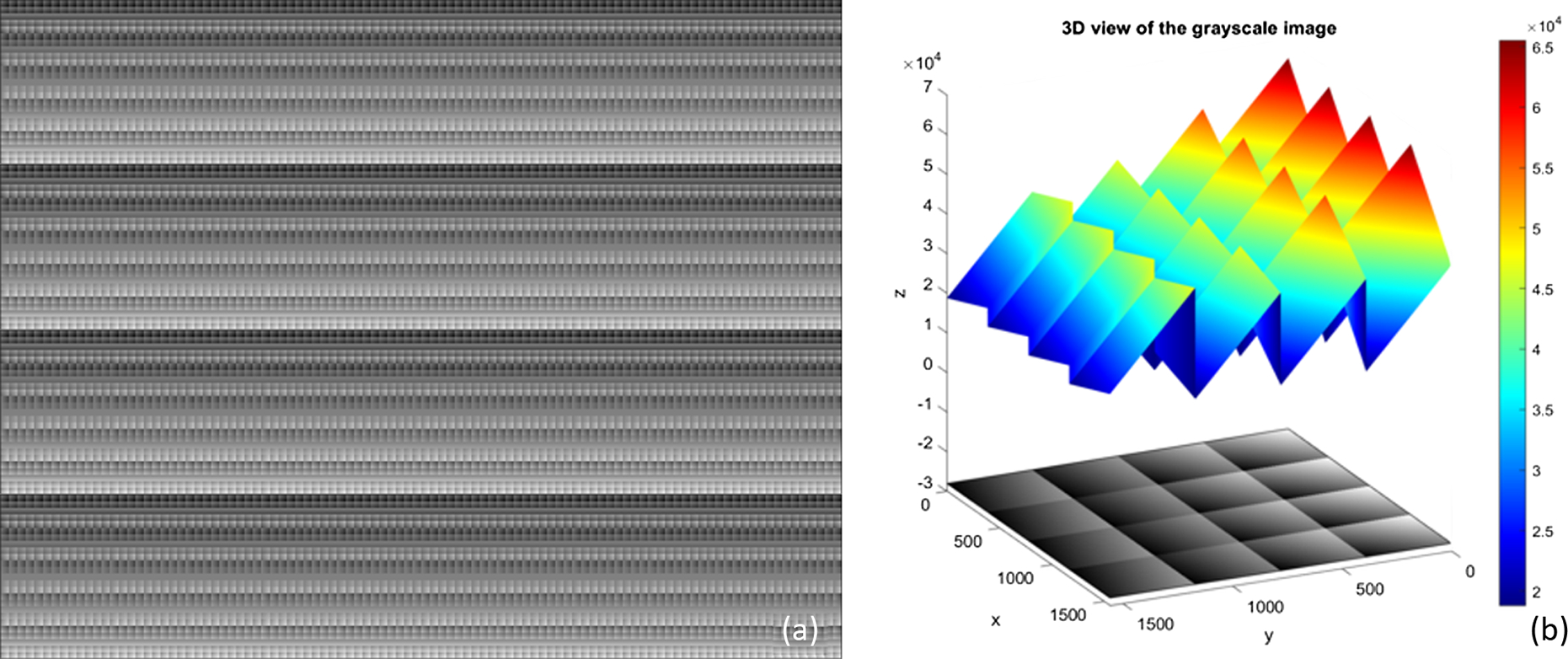
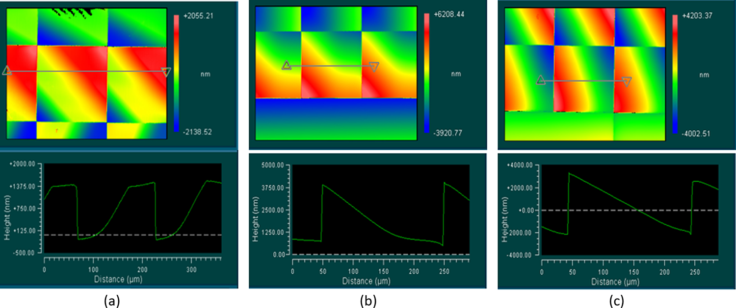
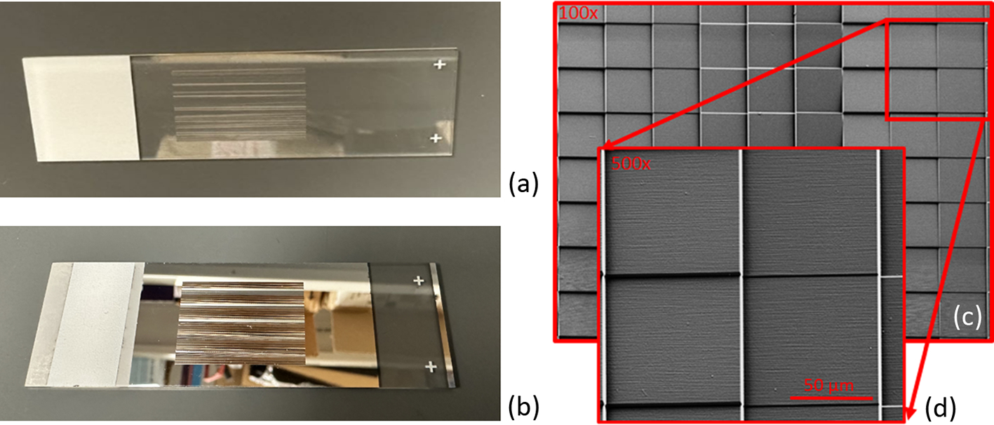
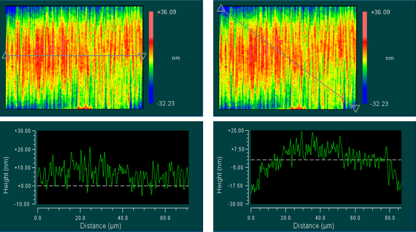
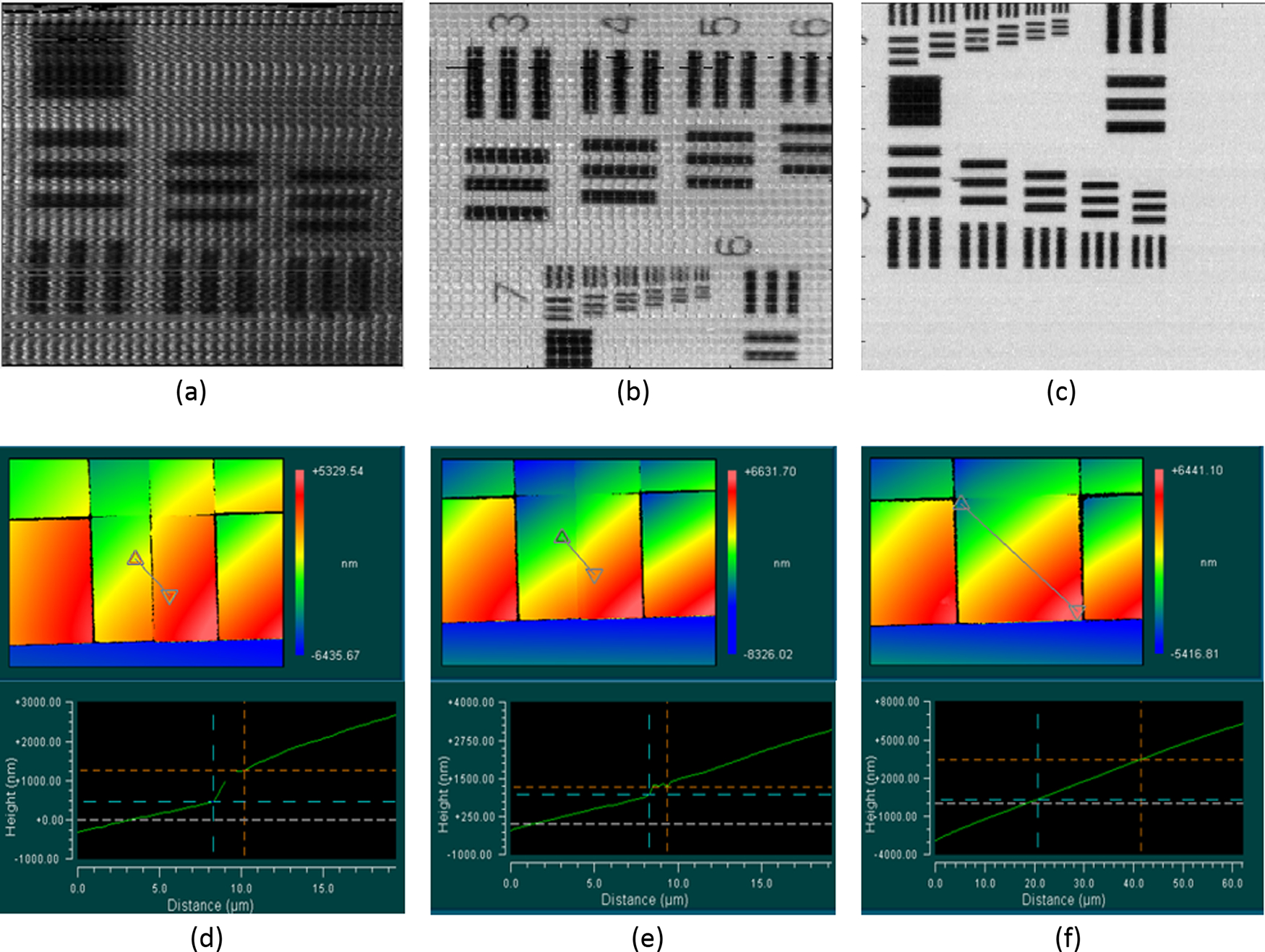
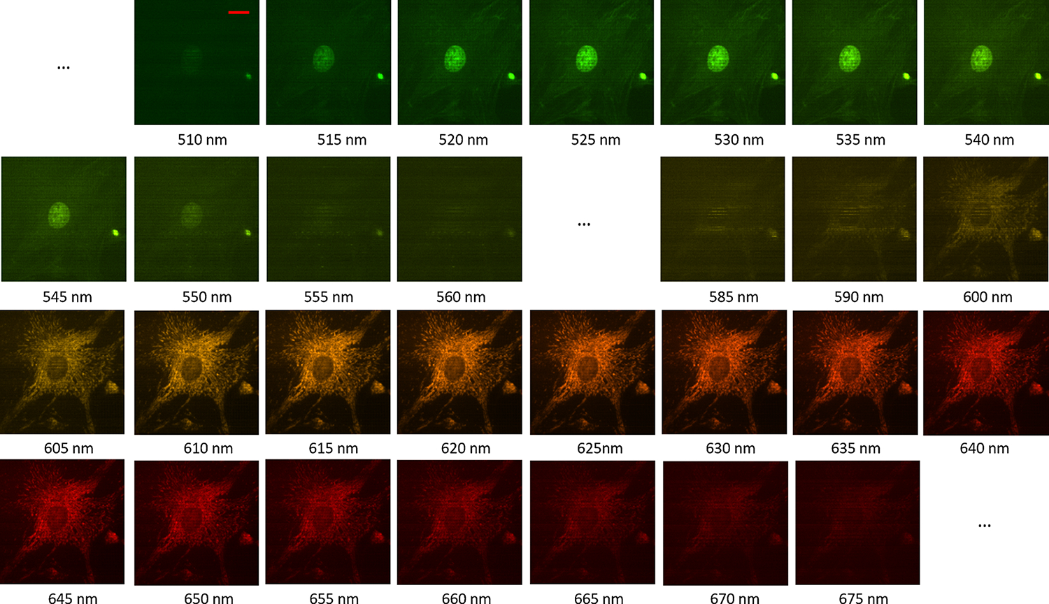
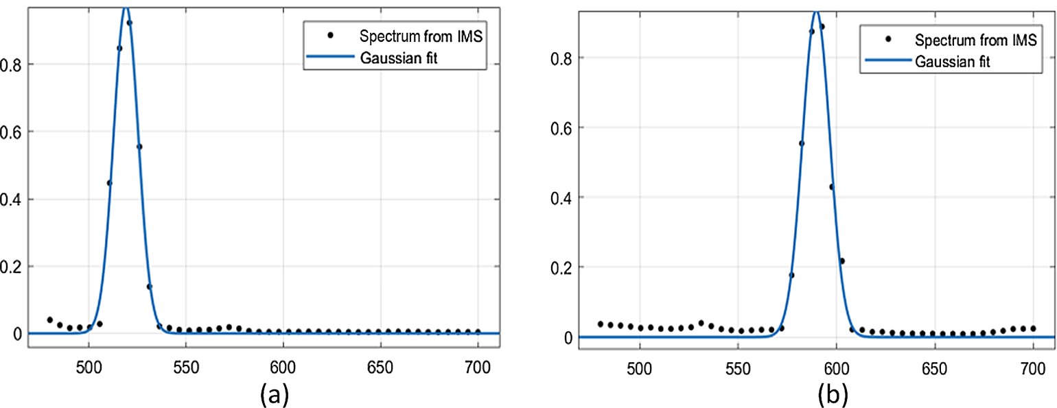
A design and fabrication technique for making high-precision and large-format multifaceted mapping mirrors is presented. The method is based on two-photon polymerization, which allows more flexibility in the mapping mirror design. The mirror fabricated in this paper consists of 36 2D tilted square pixels, instead of the continuous facet design used in diamond cutting. The paper presents a detailed discussion of the fabrication parameters and optimization process, with particular emphasis on the optimization of stitching defects by compensating for the overall tilt angle and reducing the printing field of view. The fabricated mirrors were coated with a thin layer of aluminum (93 nm) using sputter coating to enhance the reflection rate over the target wave range. The mapping mirror was characterized using a white light interferometer and a scanning electron microscope, which demonstrates its optical quality surface (with a surface roughness of 12 nm) and high-precision tilt angles (with an average of 2.03% deviation). Finally, the incorporation of one of the 3D printed mapping mirrors into an image mapping spectrometer prototype allowed for the acquisition of high-quality images of the USAF resolution target and bovine pulmonary artery endothelial cells stained with three fluorescent dyes, demonstrating the potential of this technology for practical applications.
Conflict of interest statement
Figures
References
-
- Hege EK, O’Connell D, Johnson W, Basty S, and Dereniak EL, “Hyperspectral imaging for astronomy and space surveillance,” Proc. SPIE 5159, 380–391 (2004).
-
- Rafert B, Sellar RG, Holbert E, Blatt JH, Tyler DW, Durham SE, and Newby HD, “Hyperspectral imaging Fourier transform spectrometers for astronomical and remote sensing observations,” Proc. SPIE 2198, 338–349 (1994).
-
- Gowen AA, O’Donnell CP, Cullen PJ, Downey G, and Frias JM, “Hyperspectral imaging–an emerging process analytical tool for food quality and safety control,” Trends Food Sci. Technol. 18, 590–598 (2007).
-
- Adão T, Hruška J, Pádua L, Bessa J, Peres E, Morais R, and Sousa JJ, “Hyperspectral imaging: a review on UAV-based sensors, data processing and applications for agriculture and forestry,” Remote Sens. 9, 1110 (2017).
-
- Park B and Lu R, Hyperspectral Imaging Technology in Food and Agriculture (Springer, 2015).
Grants and funding
LinkOut - more resources
Full Text Sources
