. 2023 Sep 22;9(38):eadh5260.
doi: 10.1126/sciadv.adh5260. Epub 2023 Sep 20.

An acoustically controlled helical microrobot

Affiliations

An acoustically controlled helical microrobot

Yong Deng et al. Sci Adv. .

Abstract

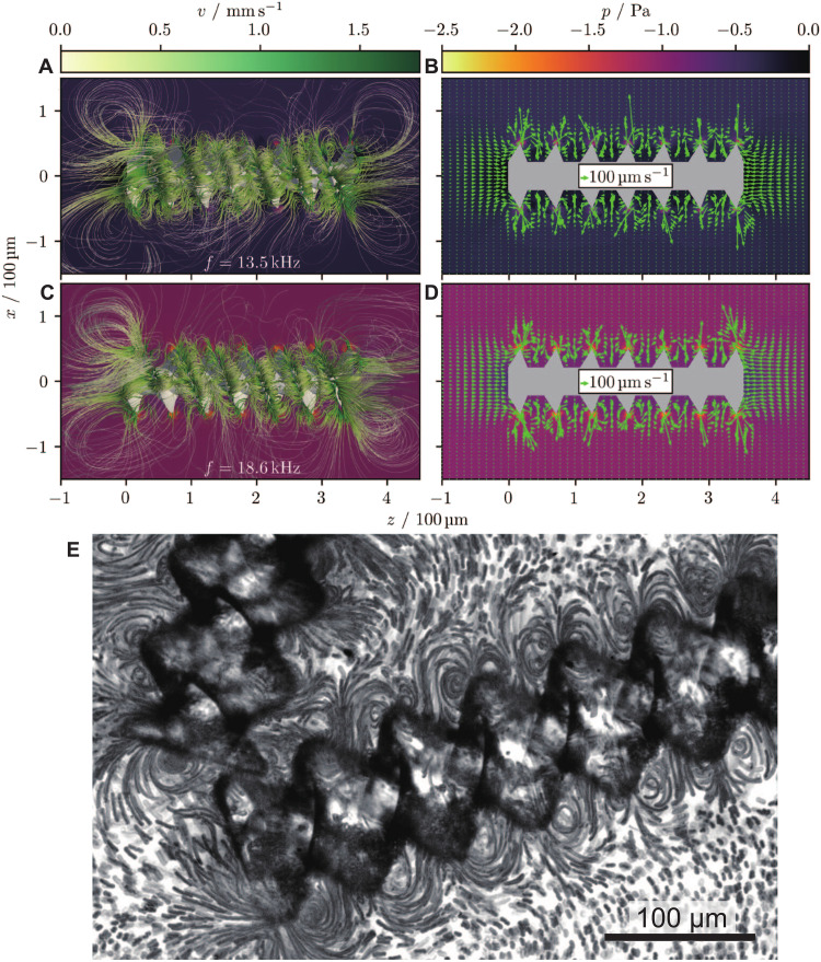
As a next-generation toolkit, microrobots can transform a wide range of fields, including micromanufacturing, electronics, microfluidics, tissue engineering, and medicine. While still in their infancy, acoustically actuated microrobots are becoming increasingly attractive. However, the interaction of acoustics with microstructure geometry is poorly understood, and its study is necessary for developing next-generation acoustically powered microrobots. We present an acoustically driven helical microrobot with a length of 350 μm and a diameter of 100 μm that is capable of locomotion using a fin-like double-helix microstructure. This microrobot responds to sound stimuli at ~12 to 19 kHz and mimics the spiral motion of natural microswimmers such as spirochetes. The asymmetric double helix interacts with the incident acoustic field, inducing a propulsion torque that causes the microrobot to rotate around its long axis. Moreover, our microrobot has the unique feature of its directionality being switchable by simply tuning the acoustic frequency. We demonstrate this locomotion in 2D and 3D artificial vasculatures using a single sound source.


Figures

Fig. 1.
Fig. 1.. Spirochete-inspired propulsion based on acoustic actuation.
(A) Micrograph showing the spiral morphology of Spirochete bacteria (51), which execute translation motion through rotation in viscosity-dominated fluids, reprinted with permission from (51). Copyright ª 2023 Yale Journal of Biology and Medicine. (B) An illustration of a wireless bioinspired robot that propels in response to an external sound field. (C) A concept schematic illustrates the use of such microrobots for noninvasive surgery in vasculatures.
Fig. 2.
Fig. 2.. Design, fabrication, and concept of the acoustically actuated helical microrobot.
(A) The acoustic helical microrobots are mass-manufactured using the two-photon lithography technique. The bottom inset shows different designs of the microrobots featuring helical vanes with radius rd = 1.0, 0.65, 0.43, and 0.22. (B) Micrograph illustrating the top view of the fabricated microrobots on a thin glass slide. The inset shows the detail of vane. (C) Side view of the fabricated microrobots. Schematic and fluorescent micrographs (right) illustrating the helical vane structures on the microrobot with rd = 0.43 and 0.22. The pink and blue colors represent the two respective levorotatory double-helix vanes developed on the microrobot. (D) Image sequences demonstrate the acoustic microrobots’ translational and rotational motion in response to an acoustic stimulus at 13.5 kHz. The insets show the clockwise rotation of the microrobot, which is indicated by the orientation of the vane geometry. (E) Schematic of the experimental setup. The polydimethylsiloxane (PDMS)–based microchannel was bonded onto a glass slide adjacent to a piezo transducer, which generates the acoustic wave field. The inset illustrates the manipulation of the microrobot within a microchannel of arbitrary shape. Scale bars, 40 μm.
Fig. 3.
Fig. 3.. Results of acoustofluidic simulations for the flow field around the microrobot.
(A to D) The simulations correspond to a particle with length of 350 μm, outer diameter of 100 μm, helicity hd = 1.08, and relative inner diameter rd = 0.43. Furthermore, the sound frequency is 13.5 kHz (A and B) and 18.6 kHz (C and D). The subfigures in the left column (A and C) show 3D streamlines in the fluid around the particle, whereas in the right column (B and D) a 2D cross section of the velocity field is shown. The pressure field is shown in the background. One can see vortices that form at the tips of the microbots’ fins (see also movie S1). All quantities shown are averaged over the last simulated wave period. The simulations were performed using the fluid dynamics solver AcoDyn. (E) Micrograph of stacked images illustrates the developed acoustic streaming around the microrobot at an excitation frequency and voltage of 18.6 kHz and 10 VPP, respectively (see also movie S1).
Fig. 4.
Fig. 4.. Translational motion of the microrobot in a circular microchannel.
(A) The microrobot exhibits left-to-right locomotion in response to an external acoustic wave at f1 = 13.5 kHz and 20 VPP. The symbol P(t) in the top schematic represents the pressure wave, while the black arrow indicates the direction of the acoustic wave field. (B) The microrobot exhibits right-to-left locomotion for f2 = 18.6 kHz and 60 VPP. (C) A microrobot illustrates its bidirectionality when switching from f1 = 13.5 kHz and 20 VPP to f2 = 18.6 kHz and 60 VPP. (D) The plot illustrates the speed profile of the microrobot during its bidirectional trajectory. (E) The microrobot’s left-to-right velocity vt1 and right-to-left velocity vt2 versus the acoustic driving voltage VPP indicate that the microrobot propels at a speed nearly proportional to VPP2 . The inset shows the corresponding log-log plot. Note that the scaling of vt2 was difficult to predict because of a lack of data points at higher voltages, as the maximum voltage is restricted by our amplifier at 60 VPP. Scale bars, 100 μm. The direction of gravity is antiparallel to the y direction (indicated by ⨀), i.e., perpendicular to the figure plane. Each data point represents the average velocity of at least three microrobots. The error bar represents the SD.
Fig. 5.
Fig. 5.. The structure-dependent behavior of the microrobots.
(A) Parametric study of the effect of the effective diameter ratio (rd = r/R) on the translation and rotation velocities of the microrobot. With decreasing rd values, microrobots exhibit faster translation, which can be attributed to increases in their vane width and surface area. The left panel illustrates the design of microrobots with rd = 1.0, 0.65, 0.43, and 0.22. Right: The distance traveled for each corresponding rd value over 10 s at the constant activation parameters of 13.5 kHz and 20 VPP; see also movie S6. Scale bar, 200 μm. (B) Plot of a microrobot’s translational velocity vt (green), angular velocity ω (blue), and rotation-induced translational velocity vrt (white) as functions of rd. (C) Parametric study of the effect of the helical pitch hd = P/(2R) on the translation and rotation velocities of the microrobot. Left: The design of microrobots with hd = 2.16, 1.08, and 0.54. Right: The distance traveled for each corresponding hd value over 6 s at 13.5 kHz and 20 VPP; see also movie S7. Scale bar, 200 μm. (D) Plot of the microrobot’s translational velocity vt (green), angular velocity ω (blue), and rotation-induced translational velocity vrt (white) as functions of hd.
Fig. 6.
Fig. 6.. Manipulation of the microrobots in a 3D artificial vasculature.
(A) A schematic illustrates the manipulation of acoustic helical microrobots in channels with different inclination angles (see also fig. S5). (B) The photograph depicts a 3D PDMS-based artificial vasculature mounted on a glass slide adjacent to a piezo transducer. The inset shows the fluorescently labeled channel with a circular cross section. (C) Concept of bidirectional motion when the excitation frequency is switched from fdown (downward) to fup (upward). (D) Superimposed images showing downward motion (fdown = 11.7 to 13.7 kHz) of microrobots in 3D channels with angles of 0°, 15°, 25°, 45°, 60°, and 75°. (E) Examples of superimposed images showing an upward propulsion (frequency fup = 14.5 to 15.1 kHz) of microrobots in 3D channels with angles of 15° and 45°. See also movies S8 and S9. Scale bars, 250 μm.

Similar articles

Cited by

References

    1. N. W. Charon, S. F. Goldstein, Genetics of motility and chemotaxis of a fascinating group of bacteria: The spirochetes. Annu. Rev. Genet. 36, 47–73 (2002). - PubMed
    1. C. Li, A. Motaleb, M. Sal, S. F. Goldstein, N. W. Charon, Spirochete periplasmic flagella and motility. J. Mol. Microbiol. Biotechnol. 2, 345–354 (2000). - PubMed
    1. A. Ghosh, D. Dasgupta, M. Pal, K. I. Morozov, A. M. Leshansky, A. Ghosh, Helical nanomachines as mobile viscometers. Adv. Funct. Mater. 28, 1705687 (2018).
    1. L. Zhang, J. J. Abbott, L. Dong, B. E. Kratochvil, D. Bell, B. J. Nelson, Artificial bacterial flagella: Fabrication and magnetic control. Appl. Phys. Lett. 94, 064107 (2009).
    1. X. Yan, Q. Zhou, M. Vincent, Y. Deng, J. Yu, J. Xu, T. Xu, T. Tang, L. Bian, Y.-X. J. Wang, K. Kostarelos, L. Zhang, Multifunctional biohybrid magnetite microrobots for imaging-guided therapy. Sci. Robot. 2, eaaq1155 (2017). - PubMed