[Preprint]. 2023 Sep 4:2023.09.01.555781.
doi: 10.1101/2023.09.01.555781.

The Egg-Counter: A novel microfluidic platform for characterization of Caenorhabditis elegans egg-laying

Affiliations

The Egg-Counter: A novel microfluidic platform for characterization of Caenorhabditis elegans egg-laying

Stephen A Banse et al. bioRxiv. .

Update in

Abstract

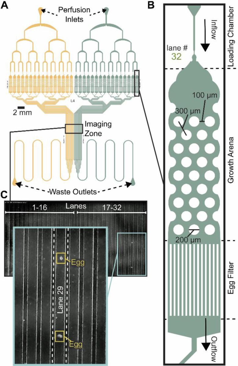
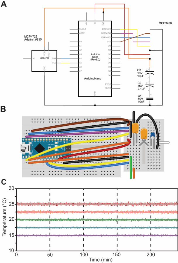
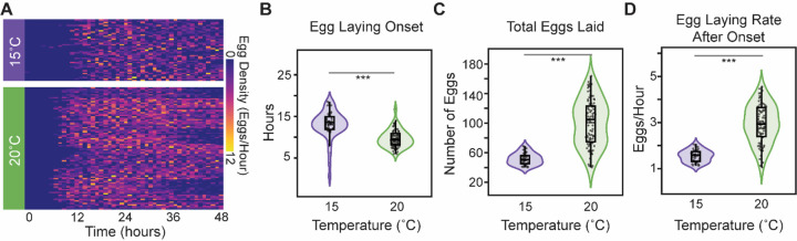
Reproduction is a fundamental process that shapes the demography of every living organism yet is often difficult to assess with high precision in animals that produce large numbers of offspring. Here, we present a novel microfluidic research platform for studying Caenorhabditis elegans' egg-laying. The platform provides higher throughput than traditional solid-media assays while providing a very high degree of temporal resolution. Additionally, the environmental control enabled by microfluidic animal husbandry allows for experimental perturbations difficult to achieve with solid-media assays. We demonstrate the platform's utility by characterizing C. elegans egg-laying behavior at two commonly used temperatures, 15 and 20°C. As expected, we observed a delayed onset of egg-laying at 15°C degrees, consistent with published temperature effects on development rate. Additionally, as seen in solid media studies, egg laying output was higher under the canonical 20°C conditions. While we validated the Egg-Counter with a study of temperature effects in wild-type animals, the platform is highly adaptable to any nematode egg-laying research where throughput or environmental control needs to be maximized without sacrificing temporal resolution.


Conflict of interest statement

Conflicts of interest The authors have no conflicts to declare.

Figures

Figure 1.
Figure 1.. Egg-Counter chip design features.
(A) Schematic of the Egg-Counter chip. The chip features two independent arrays (yellow and green) that begin with a perfusion inlet for buffer/food flow during an experiment. The fluid flows through a distribution network before entering 16 parallel animal Growth Arenas. The exit channels from each Growth Arena remain separate until after the Imaging Zone when the channels merge and continue to the Waste Outlet. Additional channel length prior to the Waste Outlet adds system resistance to minimize changes in flow rate during experiments. (B) Each of the Growth Arenas consist of three sequential features; a Loading Chamber that uses a hold and push method, to facilitate loading animals, the actual arena featuring a hexagonal pattern of pillars that promotes plate-like sinusoidal movement, and an Egg Filter that retains adults while allowing eggs to pass into the outflow. (C) The individual outflow channels are brought together in a parallel arrangement in the imaging zone. Shown is a representative image of the imaging zone at a time when two eggs laid in Growth Arena #29 were detected.
Figure 2.
Figure 2.. Egg-Counter platform.
(A) The Egg-Counter platform comprises three control systems: Fluid Control, Environmental Control, and Data Control. Fluid flow is driven by pressurizing the air in the buffer bottle to ~0.5 PSI. The buffer containing suspended bacteria is then driven through tubing with an attached vibration motor that maintains the bacterial suspension. Prior to entering the Egg-Counter chip, the fluid passes through a 5 μm filter. Egg-Counter chips are mounted on the Egg-Counter platform for environmental control. A custom acrylic platform holds a digital microscope, thermoelectric cooler (TEC), heat sink, fan, and temperature controller. The chip is mounted directly on the TEC with thermal paste to maximize thermal contact. A temperature probe mounted on the glass slide under a PDMS cover, with potential air pockets displaced by thermal paste, feeds temperature data to the temperature controller. The Temperature Controller reads the temperature from the glass surface that the animals contact and controls the TEC to maintain the setpoint temperature. Data control is performed by a fanless computer and a Temperature Monitor. The computer takes experiment parameters from the user, communicates with the Temperature Monitor (which sets the temperature on the temperature controller), and starts the experiment. The PC monitors a live feed from the digital microscope and saves all frames with detectible changes. The microcontroller maintains communication with the temperature controller and receives temperature data at 5-second intervals, ultimately transferring the temperature logs to the PC. (B) An assembled Egg-Counter platform (minus microfluidic chip and fluid tubing). (C) The Egg-Counter was designed to be scalable while minimizing the footprint. Two shelves above a counter arrangement, with the top shelf housing a single monitor (for up to 8 devices), the Data Control electronic components, and custom power supplies each capable of powering 4 devices. The middle shelf houses the Fluid Control elements. Each bottle can feed 6–8 inlets (3–4 chips) and bundling the tubing between the chips and the bottle enables a single vibration controller to service multiple lines. The bottom shelf or countertop houses the environmental control platform, which is built to maintain the electronics in an elevated position. This configuration helps to separate the pressurized fluid and the electronic components.
Figure 3.
Figure 3.. Egg-Counter Temperature Monitor.
(A) Electrical schematic and (B) breadboard diagram for the Egg-Counter Temperature Monitor. Parts list and necessary software are available in online supplements and respectively. (C) Representative temperature data from two experimental runs (shown in light and dark shades) at five temperature conditions covering the standard growth range of C. elegans (15°C purple, 17.5°C blue, 20°C green, 22.5°C orange, and 25°C red).
Figure 4.
Figure 4.. Temperature effects on egg laying
(A) Heat map of the number of eggs laid in 1-hour windows over the course of the 48-hour experiment at the two tested temperatures, (B) The egg-laying onset time at the five experimental temperatures. (C) The total number of observed eggs laid during the 48-hour experiment. (D) The egg-laying rate, defined as the slope from a linear regression for cumulative number of eggs laid versus time. All panels use the same color key to distinguish the two temperatures (15°C purple and 20°C green). Presented statistical analyses (*** p<0.001) are nonparametric Wilcoxon comparisons.
Figure 5.
Figure 5.. Egg-laying trajectories in the Egg-Counter.
(A) The distribution of egg laying events in time is distributed such that two inter-egg intervals exist. (B) Egg-laying trajectories from the time of egg-laying onset for animals at 20°C degrees. Shown are data from 12 different Egg-Counter chips, with the traces colored by experimental chip. The figure inset shows a 5-hour segment with one trajectory highlighted to illustrate the observed “bursty” pattern of periods with no eggs laid, punctuated by bouts of active egg laying. In the example, bursts of 3, 6, and 4 laid eggs are noted. (C) The distribution of within-burst (WBI) intervals (N = 1,103 at 15°C and 4,702 at 20°C), and (D) the distribution of inter-burst (IBI) intervals (N = 1,126 at 15°C and 4163 at 20°C) with their respective mean and 95% confidence interval is shown.

References

    1. Carey J. R. & Roach D. Biodemography: An Introduction to Concepts and Methods. (Princeton University Press, 2020).
    1. Cury K. M., Prud’homme B. & Gompel N. A short guide to insect oviposition: when, where and how to lay an egg. J. Neurogenet. 33, 75–89 (2019). - PubMed
    1. Chin S. G., Maguire S. E., Huoviala P., Jefferis G. S. X. E. & Potter C. J. Olfactory neurons and brain centers directing oviposition decisions in Drosophila. Cell Rep. 24, 1667–1678 (2018). - PMC - PubMed
    1. Chen Y. & Amrein H. Ionotropic receptors mediate Drosophila oviposition preference through sour gustatory receptor neurons. Curr. Biol. 27, 2741–2750.e4 (2017). - PMC - PubMed
    1. Dweck H. K. M. et al. Olfactory preference for egg laying on citrus substrates in Drosophila. Curr. Biol. 23, 2472–2480 (2013). - PubMed

Publication types