

A Framework for Predicting X-Nuclei Transmitter Gain Using 1H Signal
- PMID: 37736981
- PMCID: PMC10514872
- DOI: 10.3390/tomography9050128
A Framework for Predicting X-Nuclei Transmitter Gain Using 1H Signal
Abstract
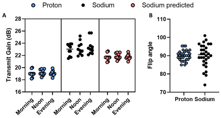
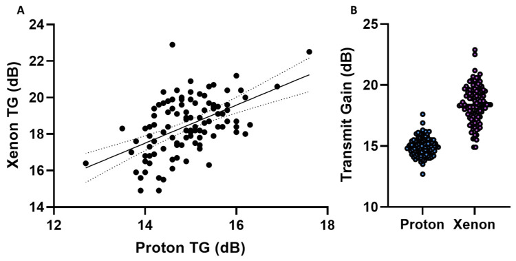
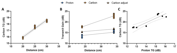
Commercial human MR scanners are optimised for proton imaging, containing sophisticated prescan algorithms with setting parameters such as RF transmit gain and power. These are not optimal for X-nuclear application and are challenging to apply to hyperpolarised experiments, where the non-renewable magnetisation signal changes during the experiment. We hypothesised that, despite the complex and inherently nonlinear electrodynamic physics underlying coil loading and spatial variation, simple linear regression would be sufficient to accurately predict X-nuclear transmit gain based on concomitantly acquired data from the proton body coil. We collected data across 156 scan visits at two sites as part of ongoing studies investigating sodium, hyperpolarised carbon, and hyperpolarised xenon. We demonstrate that simple linear regression is able to accurately predict sodium, carbon, or xenon transmit gain as a function of position and proton gain, with variation that is less than the intrasubject variability. In conclusion, sites running multinuclear studies may be able to remove the time-consuming need to separately acquire X-nuclear reference power calibration, inferring it from the proton instead.
Trial registration: ClinicalTrials.gov NCT05215938.
Keywords: X-nuclei imaging; carbon; magnetic resonance imaging; radio frequency setting; sodium; xenon.
Conflict of interest statement
M.V. and R.F.S. are employees of GE HealthCare. The authors report no conflicts of interest. The authors alone are responsible for the content and writing of the paper.
Figures
References
-
- Banks W.P., Company H. Nutation Angle Measurement During Mri Prescan. Search. 1980:3–6.
-
- Niedbalski P.J., Hall C.S., Castro M., Eddy R.L., Rayment J.H., Svenningsen S., Parraga G., Zanette B., Santyr G.E., Thomen R.P., et al. Protocols for multi-site trials using hyperpolarized 129Xe MRI for imaging of ventilation, alveolar-airspace size, and gas exchange: A position paper from the 129Xe MRI clinical trials consortium. Magn. Reson. Med. 2021;86:2966–2986. doi: 10.1002/mrm.28985. - DOI - PubMed
Publication types
MeSH terms
Substances
Associated data
Grants and funding
LinkOut - more resources
Full Text Sources
Medical
