. 2023 Sep 21;83(18):3283-3302.e5.
doi: 10.1016/j.molcel.2023.08.025.

Implications of a multiscale structure of the yeast nuclear pore complex

Affiliations

Implications of a multiscale structure of the yeast nuclear pore complex

Christopher W Akey et al. Mol Cell. .

Abstract

Nuclear pore complexes (NPCs) direct the nucleocytoplasmic transport of macromolecules. Here, we provide a composite multiscale structure of the yeast NPC, based on improved 3D density maps from cryogenic electron microscopy and AlphaFold2 models. Key features of the inner and outer rings were integrated into a comprehensive model. We resolved flexible connectors that tie together the core scaffold, along with equatorial transmembrane complexes and a lumenal ring that anchor this channel within the pore membrane. The organization of the nuclear double outer ring reveals an architecture that may be shared with ancestral NPCs. Additional connections between the core scaffold and the central transporter suggest that under certain conditions, a degree of local organization is present at the periphery of the transport machinery. These connectors may couple conformational changes in the scaffold to the central transporter to modulate transport. Collectively, this analysis provides insights into assembly, transport, and NPC evolution.

Keywords: AlphaFold2 modeling; FG repeats; computed structure models; cryo-EM; cryogenic electron microscopy; nuclear pore complex; nucleocytoplasmic transport; single-particle analysis.


Conflict of interest statement

Declaration of interests The authors declare no competing interests.

Figures

Figure 1.
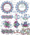
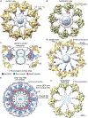
Figure 1.. A composite multiscale 3D structure of the isolated yeast NPC
Nine 3D density maps were segmented into 16 regions to highlight functional sub-assemblies as indicated in the color-coded key. Labels: nuclear double outer ring (NR), inner ring (IR), and cytoplasmic outer ring (CR). (A) A top view from the nuclear compartment reveals the double outer ring with associated orphan Nups and linker domains. (B) The view in (A) has been rotated 30° counterclockwise about the vertical axis. (C) A view from the pore membrane; the lipid-detergent micelle that encircles the inner ring is not shown. (D) A cut-away view oriented as in (C) to reveal the co-axial rings, along with membrane anchor points (TMDs) and the hourglass-shaped central transporter/plug.
Figure 2.
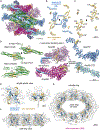
Figure 2.. Inner ring structure and interactions between spokes
(A) The inner ring and associated membrane protein densities (silver) within the micelle ring are shown. The inner ring has been segmented into an inner layer (green), an intermediate adaptin-like layer (dark pink), and the membrane-interacting layer (light blue). (B) The highly fenestrated architecture of the inner ring with gaps (asterisks) and membrane-spanning regions are revealed in a cross-section that also shows the central channel. A single spoke is outlined (dashed rhomboid). (C) A “half ring” view of the inner ring is viewed from the pore membrane; the local 2-fold axis for the center spoke is indicated with a black ellipse. (D) Central cross-sections through the spoke with molecular models depicted as rods are viewed from the side and top to show the open architecture with gaps and voids (asterisks). A local 2-fold axis in the plane is indicated with an arrow and “2”. (E) A molecular model for Nups within the spoke is shown as “cylinders and planks.” Three views from left to right: a front view from the central channel, a side view, and a view from the cytoplasm. All views have platform density (silver) and single rod-like connectors in blue and gold. (F) Molecular model for three spokes in the inner ring. (G) Two Nup170 molecules form a major contact between adjacent spokes and may interact with an Ndc1 dimer at the local 2-fold axis with their β-propellers (βs). (H) Three inter-spoke contacts are shown: a contact between adjacent Nsp1 complexes and a pair of symmetry-related contacts between the Nup192 NTD and Nup188 CTD tail that are indicated with black arrows. One Nup188-Nup192 contact is outlined with a dashed oval. Nic96 and new connectors are shown in blue and gold ribbons.
Figure 3.
Figure 3.. Connectors in the inner ring tie together Nup layers in the spoke
(A) A front view of the spoke with Nups displayed as ribbons and connectors as segmented and color-coded density maps: Nic96 NTD connectors (blue) and new connectors in gold. (B) A front view is shown along the local 2-fold axis (black ellipse) with spoke connectors as cylinders and strands in their local density. (C) Newly identified and grouped connectors labeled C1 to C9 (and their symmetry mates: C1′–C9′) start at the inner layer and extend into the membrane-interacting layer (Table S3). (D) Interactions between new connectors (gold) and their Nup partners. (E) Color-coded electron density for Nic96 NTD and new connectors are shown for a single transparent spoke (front and top views). (F) All inner ring connectors are shown in a half ring view. (G) Connectors within the inner ring are viewed in a 45° tilt view.
Figure 4.
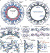
Figure 4.. Membrane anchor complexes for the inner ring
(A) An inner ring-TMD lumenal ring complex is viewed along the C8 axis with one protomer outlined (dashed rhomboid). The lumenal ring (LR) is light silver, TMDs for Pom34-Pom152 and Ndc1 are in gray, and the micelle ring is white. (B) A molecular model for the membrane-interacting layer is juxtaposed to Nup157 and Nup170 TMD anchor sites and the lumenal ring. (C) A close up of the Nup157 and Nup170 anchor sites; Nup53-Nup59 heterodimers (brown) are in close proximity to Nup170 molecules at the interface between spokes. (D) Orthogonal views are shown of the Pom34-Pom152 TMD map with gray cylinders to mark 10 α helices aligned in two parallel rows of 5. The protomer in this dimeric complex may correspond to an α-helical bundle formed by rods 1–2 and 5–7 (see text). (E) Top: an improved 3D density map for the lumenal ring viewed from the NE lumen. Local 2-fold axes are indicated with black ellipses, and 10 densities are numbered in one repeat. Bottom: 10 Ig-like features (red) are present in the lumenal ring protomer. (F) Anchor sites in the membrane-interacting layer as viewed from the pore membrane. These include Nup157 and Nup170 β-propellers at local 2-fold axes and likely contributions from Nup53-Nup59 heterodimers (see text). (G) Cross-sections centered on anchor complexes for Nup157 (left) and Ndc1 (right) are viewed at right angles to the local 2-fold axes.
Figure 5.
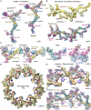
Figure 5.. Conformation of Y-complexes and characterization of orphan Nup densities and linker domains in the double outer ring
(A) Left: ribbon model for the proximal Nup84 Y-complex oriented vertically. Right: model of the distal Y-complex with the vertical offset that is present in the double ring protomer. (B) Top: 3D density map with four Nup84 complexes in two protomers of the double outer ring. Bottom: molecular model of two adjacent protomers with notable features labeled. A non-canonical interaction of the distal Nup133 β-propeller with the spur of the proximal Nup133 is marked (blue dot). (C) Four panels with close-up views of notable regions in Nup84 Y-complexes, including the Y-junction/hub, a non-canonical bulge in the distal Y-complex, and a tripod of membrane-interacting β-propellers. The black dot in panel 2 marks a lateral contact between Nup85 and Nup84 in an adjacent protomer. (D) Overview of a full double outer ring with putative Nic96 CTDs (O1 and O2; dark brown), possible Nup188–192 orphans (O3 and O4; medium brown), linker domains (L1, dark blue; L2, purple), proximal and distal Y-complexes (gold and light yellow). (E) A zoomed-in view of the full double outer ring with models of the double Y-protomers and orphans. (F) A similar view to (E) without orphan Nups; semi-transparent L1 and L2 linker domains reveal their respective footprints on Nup188 in the spoke (above the C7– C8 connectors) and the Nup53–Nup59 heterodimer. A contact site for L2 on the proximal Y-complex is indicated (asterisk) along with a non-canonical interaction of the distal Nup133 β-propeller (blue dot).
Figure 6.
Figure 6.. Bridging FG connectors between the core scaffold and central transporter
(A) A map of the full nuclear double outer ring (gold, NR) is docked within a density map from the entire NPC (transparent gray). A thick slab shows connectors from the double outer ring to the central transporter/plug (blue dot), which were modeled with blue rods for visualization. (B) A map of the single cytoplasmic outer ring (bronze, CR) is docked into a map of the entire NPC. This view reveals FG connectors (red dot and rods) appropriately positioned to originate from the Nup82 complex associated with the single outer ring. (C) Modeled FG connectors are present at three levels along the central channel in this central cross-section; labels: inner ring (IR), lumenal ring (LR), and linker domain 1 (L1). Possible contact sites on the plug (dotted circles) and a color key for FG connectors are shown. (D) A thick section of the double outer ring viewed along the central C8 axis with modeled FG-connector bundles to the central transporter. (D)–(F) are viewed from the nuclear side. (E) Thick section of the inner ring-TMD lumenal ring complex with modeled FG connectors from Nsp1 complexes., (F) Thick section of the cytoplasmic outer ring with modeled FG connectors.
Figure 7.
Figure 7.. Nup145 topology diagram and interplay between the core scaffold and central transporter/plug
(A) Left: proposed Nup145 topology with a region of the double outer ring shown as an outset in the dashed box from the right-hand panel. Nup145N binding sites are indicated by gray rectangles. Right: schematic model of the form II yeast NPC with FG connectors to the plug/central transporter and their contact sites (dashed circles). (B) Radial expansion of the NPC scaffold may trigger functional changes in the central transporter. FG connectors appear to be maintained in the transition; connectors are color-coded (Figure 6C) based on location and possible Nup anchor. Left: transport factors with cargo may be entrapped within the FG mesh of the plug-like transporter. Right: reorganization of the core scaffold and FG mesh promotes translocation of transport factor-cargo complexes.

Similar articles

Cited by

References

    1. Hoogenboom BW, Hough LE, Lemke EA, Lim RYH, Onck PR, and Zilman A. (2021). Physics of the nuclear pore complex: theory, modeling and experiment. Phys. Rep 921, 1–53. 10.1016/j.physrep.2021.03.003. - DOI - PMC - PubMed
    1. Dultz E, Wojtynek M, Medalia O, and Onischenko E. (2022). The nuclear pore complex: birth, life, and death of a cellular behemoth. Cells 11, 1456. 10.3390/cells11091456. - DOI - PMC - PubMed
    1. Petrovic S, Mobbs GW, Bley CJ, Nie S, Patke A, and Hoelz A. (2022). Structure and function of the nuclear pore complex. Cold Spring Harb. Perspect. Biol 14, a041264. 10.1101/cshperspect.a041264. - DOI - PMC - PubMed
    1. Sakuma S, and D’Angelo MA (2017). The roles of the nuclear pore complex in cellular dysfunction, aging and disease. Semin. Cell Dev. Biol 68, 72–84. 10.1016/j.semcdb.2017.05.006. - DOI - PMC - PubMed
    1. Allegretti M, Zimmerli CE, Rantos V, Wilfling F, Ronchi P, Fung HKH, Lee CW, Hagen W, Turoňová B, Karius K, et al. (2020). In-cell architecture of the nuclear pore and snapshots of its turnover. Nature 586, 796–800. 10.1038/s41586-020-2670-5. - DOI - PubMed

Publication types

MeSH terms

Substances