Case Reports
. 2023 May 16;7(5):100188.
doi: 10.1016/j.shj.2023.100188. eCollection 2023 Sep.

The Added Value of Preprocedural Cardiac Computed Tomography in Planning Left Atrial Appendage Closure With the Watchman FLX Device

Affiliations
Case Reports

The Added Value of Preprocedural Cardiac Computed Tomography in Planning Left Atrial Appendage Closure With the Watchman FLX Device

Joseph Kassab et al. Struct Heart. .

Abstract

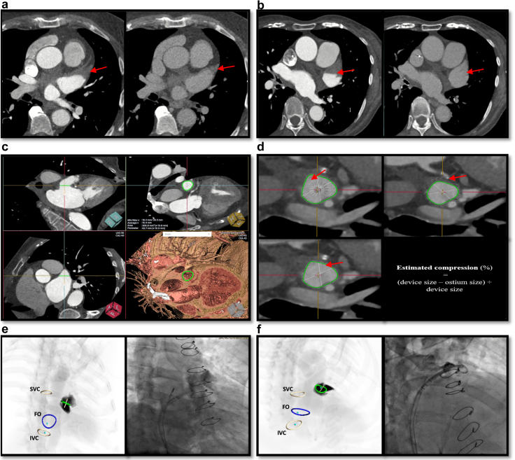
•Cardiac computed tomography (CCT) can be used as a useful complementary tool in preprocedural planning of left atrial appendage closure.•CCT planning includes assessing exclusion criteria, device sizing, sheath selection, anticipating challenging anatomies, and transseptal puncture planning.•Procedural 3D intracardiac echocardiography (3D-ICE) is increasingly being used instead of transesophageal echocardiography. In this setting, preprocedural CCT is useful to compensate for 3D ICE's reduced resolution.

Keywords: Cardiac computed tomography; Intracardiac echocardiography; Left atrial appendage closure; Preprocedural planning; Transesophageal echocardiography.


Conflict of interest statement

Serge C. Harb is on the advisory board for TruPlan and a consultant/speaker for Boston Scientific. The other authors had no conflicts to declare.

Figures

Figure 1
Figure 1
Preprocedural planning with CCT: Assessing exclusion criteria and device sizing. LAA thrombus is a contraindication for transcatheter LAAC. It appears on CCT as a hypoattenuating filling defect (a, left panel) that persists during the delayed phase (a, right panel), while slow flow, which can also have a similar appearance (b, left panel), resolves on the delayed acquisition (b, right panel). Using CCT, the LAA ostium (c) can be measured, and an appropriate device chosen (d, left lower panel). The optimal device size is the next size up (3–6 mm larger) from the maximal ostium diameter. Thus, after deployment, the device should be compressed by approximately 8% to 20% of its original size (d, right lower panel). Undersizing (d, left upper panel) can lead to device embolization and peridevice leaks, whereas oversizing (d, right upper panel) can result in prominent “shoulders,” erosion, and overcompression. Simulated fluoroscopic views (e, left panel and f, left panel) can also be generated. The RAO-CAUD (e) and RAO-CRAN (f) are the most commonly used. Abbreviations: CCT, cardiac computed tomography; FO, fossa ovalis; IVC, inferior vena cava; LAA, left atrial appendage; LAAC, left atrial appendage closure; RAO-CAUD, right anterior oblique-caudal; RAO-CRAN, right anterior oblique-cranial; SVC, superior vena cava.
Figure 2
Figure 2
Left atrial appendage challenging anatomies and transseptal puncture planning. CCT can anticipate complex LAA anatomies, like proximal lobes (a) or prominent pectinates and shallow depth (b). Transseptal puncture (TSP) is a key component for procedural success. A TSP that allows alignment with the working depth (WD) of the LAA (orthogonal to the landing zone) is key for optimal device deployment. First, the WD is defined (c, left panel), and the FO is segmented (c, right panel). Then, after aligning the crosshairs with the WD, the operator scrolls until the coaxial plane meets the FO (d, left panel). The TSP point can then be localized and visualized (d, right panel). CCT can also assess LAA orientation and help choose the optimal sheath curvature required to be coaxial. Superior and anterior LAA orientation (e) is the most frequently encountered, while other LAA orientations like medial (f, upper panels) and posterior (f, lower panels) are less common. Abbreviations: A, anterior; CCT, cardiac computed tomography; FO, fossa ovalis; I, inferior; LAA, left atrial appendage; P, posterior; S, superior.
Figure 3
Figure 3
Proper assessment of the LAA working depth by CCT. A male patient in his seventies was referred for LAAC. A Watchman placement was attempted at another center but was unsuccessful due to a described shallow working depth and a very sharp anterior “windsock” LAA morphology (a). He was referred to our institution where CCT planning was used. Image b showcases the precise morphology of the LAA with accurate measurement of the ostium (landing zone) dimensions and working depth (WD, arrow). The WD is defined as the depth orthogonal to the landing zone (c, arrows). Contrast with the absolute depth (c, red line) which should not be used. An appropriate device size was selected. In this case, a Watchman FLX 27mm device and a double curve were used with an estimated compression rate of 19%. LAAC was performed and procedural TEE showed successful deployment of the device with no evidence of residual flow or paradevice leak (d). Abbreviations: CCT, cardiac computed tomography; LAA, left atrial appendage; LAAC, left atrial appendage closure; TEE, transesophageal echocardiography.
Figure 4
Figure 4
Left atrial accessory appendage (LAAA) identification by CCT. The prevalence of LAAA is between 10% and 28% and its presence may be associated with higher risk of stroke. A male patient in his sixties was referred for LAAC. On preprocedural cardiac CT, a LAAA, which was not seen on the preprocedural TEE, was identified in the anterior and superior portion of the left atrium (Image a, red arrows) and medial to the LAA (Image a, yellow arrows). Subsequently, the decision to close both the LAA and the LAAA was made. During the procedure, a Watchman FLX 27mm device was used to seal the LAA with no residual paradevice leak seen. Then, the LAAA was searched for and identified by the intraprocedural TEE (Image b, arrows), and a 6mm AVP was successfully deployed (Image c, arrows). Image d showcases the follow-up CCT with the 2 implanted devices immediately after the procedure (AVP–red arrows and FLX–yellow arrow). Abbreviations: AVP, Amplatzer vascular plug; CCT, cardiac computed tomography; LAA, left atrial appendage; LAAC, left atrial appendage closure; TEE, transesophageal echocardiography.
Figure 5
Figure 5
CCT as an alternative for preprocedural TEE. A male patient in his eighties with prior esophageal varices was recommended for LAAC. He agreed to the procedure but preferred not to undergo TEE due to the risks associated with his previous esophageal disease history. Thus, CCT was used for preprocedural planning and 3D-ICE for guidance. The LAA dimensions and morphology were evaluated (a) and the transseptal puncture (TSP) was simulated by CCT. Then, with 3D-ICE guidance, the LAA was reassessed and its size confirmed (b). Note the lower spatial and temporal resolution of 3D-ICE (Supplemental Video 1). A pigtail catheter was placed in the LAA, and a 27mm Watchman FLX device was adequately deployed, under 3D-ICE guidance, with an appropriate compression rate (c). No leak was detected by Doppler and the device was released without any immediate complication (d). Abbreviations: CCT, cardiac computed tomography; LAA, left atrial appendage; LAAC, left atrial appendage closure; TEE, transesophageal echocardiography.
Figure 6
Figure 6
Optimizing the transseptal puncture (TSP) location. An elderly female patient was referred for LAAC. The initial TSP was mid in both the superior-inferior (S-I) and anteroposterior (A-P) planes (a, panels 1, 2 and Supplemental Video 2). The sheath did not end up coaxial (a, panel 3) and the device had a prominent shoulder (a, panel 4). Therefore, the plan was for another TSP that would allow a more coaxial approach, and the CCT was reviewed. First, the working depth (WD) was identified (b, panel 1), and the FO segmented (b, panel 2). Then, after defining the plane coaxial with the WD (b, panel 3), the image was scrolled to meet the FO (b, panel 4 and Supplemental Video 3), and the optimal TSP was identified (b, panels 5 and 6). A new more posterior TSP (c, panels 1, 2, and Supplemental Videos 4 and 5) was thus re-attempted, leading to a more coaxial access (c, panel 3) and optimal device deployment (c, panel 4). Abbreviations: CCT, cardiac computed tomography; LAAC, left atrial appendage closure; FO, fossa ovalis.

Similar articles

Cited by

  • Measure twice, implant once.
    Krishnan K, Saleem M. Krishnan K, et al. J Interv Card Electrophysiol. 2024 Jun;67(4):689-690. doi: 10.1007/s10840-024-01740-y. Epub 2024 Feb 3. J Interv Card Electrophysiol. 2024. PMID: 38308736 No abstract available.

References

    1. Troupis J., Crossett M., Scneider-Kolsky M., Nandurkar D. Presence of accessory left atrial appendage/diverticula in a population with atrial fibrillation compared with those in sinus rhythm: a retrospective review. Int J Cardiovasc Imaging. 2012;28:375–380. - PubMed
    1. Nagai T., Fujii A., Nishimura K., et al. Large thrombus originating from left atrial diverticulum: a new concern for catheter ablation of atrial fibrillation. Circulation. 2011;124:1086–1088. - PubMed

Publication types

LinkOut - more resources