. 2023 Sep 14;8(5):427.
doi: 10.3390/biomimetics8050427.

A Navigation Path Search and Optimization Method for Mobile Robots Based on the Rat Brain's Cognitive Mechanism

Affiliations

A Navigation Path Search and Optimization Method for Mobile Robots Based on the Rat Brain's Cognitive Mechanism

Yishen Liao et al. Biomimetics (Basel). .

Abstract

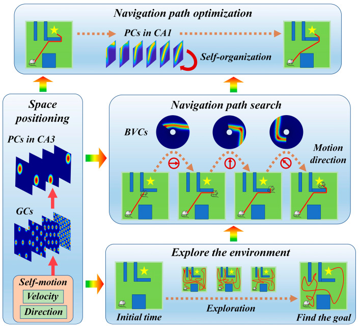
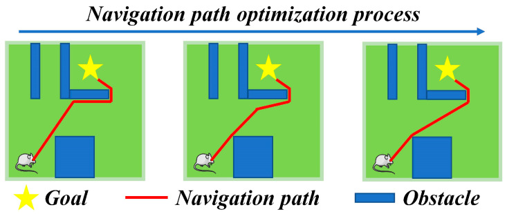
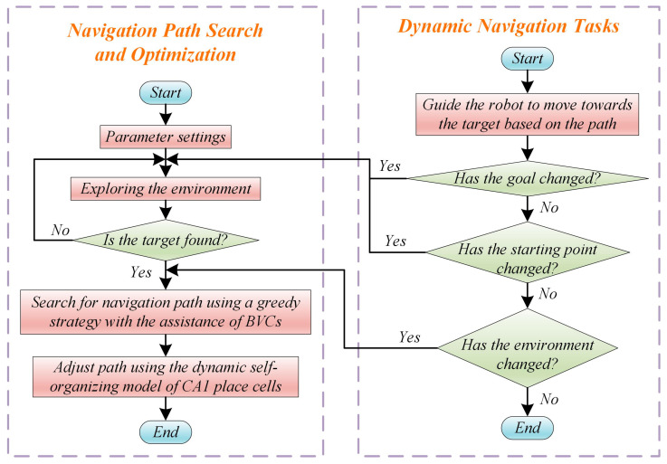
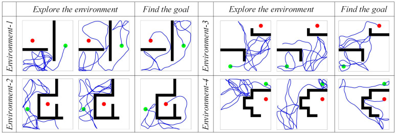
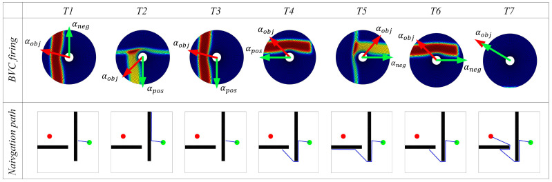
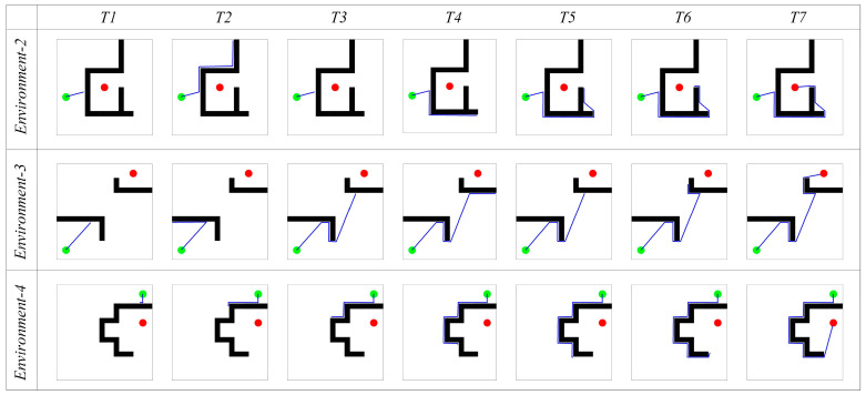
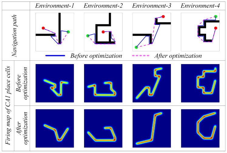
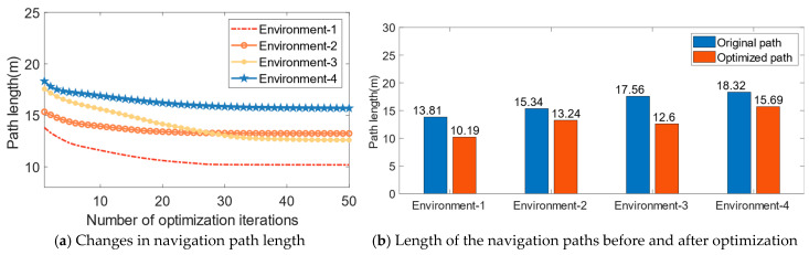
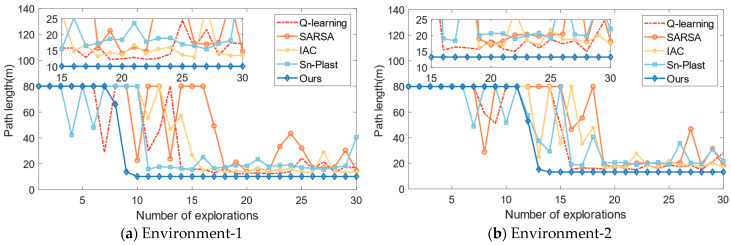
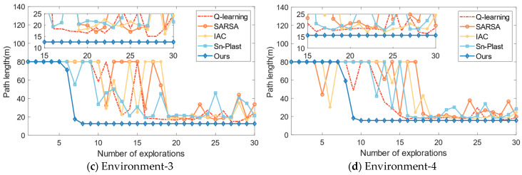
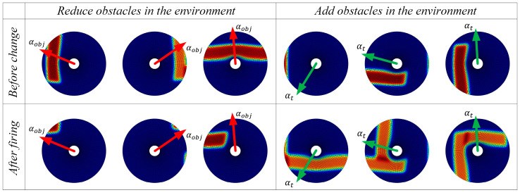
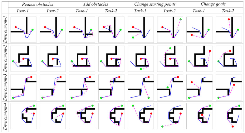
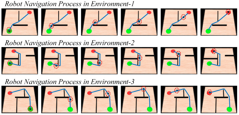
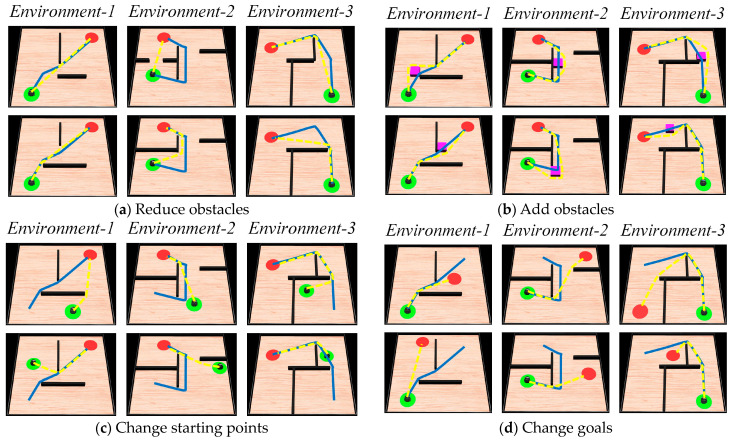
Rats possess exceptional navigational abilities, allowing them to adaptively adjust their navigation paths based on the environmental structure. This remarkable ability is attributed to the interactions and regulatory mechanisms among various spatial cells within the rat's brain. Based on these, this paper proposes a navigation path search and optimization method for mobile robots based on the rat brain's cognitive mechanism. The aim is to enhance the navigation efficiency of mobile robots. The mechanism of this method is based on developing a navigation habit. Firstly, the robot explores the environment to search for the navigation goal. Then, with the assistance of boundary vector cells, the greedy strategy is used to guide the robot in generating a locally optimal path. Once the navigation path is generated, a dynamic self-organizing model based on the hippocampal CA1 place cells is constructed to further optimize the navigation path. To validate the effectiveness of the method, this paper designs several 2D simulation experiments and 3D robot simulation experiments, and compares the proposed method with various algorithms. The experimental results demonstrate that the proposed method not only surpasses other algorithms in terms of path planning efficiency but also yields the shortest navigation path. Moreover, the method exhibits good adaptability to dynamic navigation tasks.

Keywords: boundary vector cells; mobile robots; navigation path; optimization; place cells.


Conflict of interest statement

The authors declare no conflict of interest.

Figures

Figure 1
Figure 1
The overall operational mechanism of the method.
Figure 2
Figure 2
The diagrams illustrating the angles αpos and αneg.
Figure 3
Figure 3
Operation mechanism of navigation path segment optimization.
Figure 4
Figure 4
Operation process of the navigation method.
Figure 5
Figure 5
The motion trajectories of the agent in the spatial regions. In the figures, the green circle represents the navigation starting point, the red circle represents the navigation endpoint, the black wall represents the obstacle, and the blue line represents the robot’s motion trajectory.
Figure 6
Figure 6
Experimental results of path searching process of the agent in environment 1. In the figures, the green circle represents the navigation starting point, the red circle represents the navigation endpoint, the black wall represents the obstacle, the blue line represents the robot’s navigation path, and the columns represent successive time points during the simulation.
Figure 7
Figure 7
Experimental results of path searching process of the agent in environment 2, 3, and 4. In the figures, the green circle represents the navigation starting point, the red circle represents the navigation endpoint, the black wall represents the obstacle, the blue line represents the robot’s navigation path, and the columns represent successive time points during the simulation.
Figure 8
Figure 8
Experimental results before and after navigation path optimization. In the figures, the green circle represents the navigation starting point, the red circle represents the navigation endpoint, the black wall represents the obstacle, the blue line represents the robot’s navigation path before optimization, and the pink dashed line represents the robot’s navigation path after optimization.
Figure 9
Figure 9
Path length results for navigation path optimization.
Figure 10
Figure 10
The variation of path length for each algorithm with increasing exploration iterations.
Figure 10
Figure 10
The variation of path length for each algorithm with increasing exploration iterations.
Figure 11
Figure 11
Firing effects of the boundary vector cell sensing the changes in obstacles.
Figure 12
Figure 12
The adjustment effect of navigation paths in dynamic navigation tasks. In the figures, the green circle represents the navigation starting point, the red circle represents the navigation endpoint, the black wall represents the obstacle, the blue line represents the robot’s original navigation path, and the pink dashed line represents the robot’s new navigation path.
Figure 13
Figure 13
The variation of path length in dynamic navigation experiments.
Figure 13
Figure 13
The variation of path length in dynamic navigation experiments.
Figure 14
Figure 14
Physical structure diagram of the mobile robot.
Figure 15
Figure 15
Mobile robot’s motion trajectory during the exploration process. In the figures, the green circle represents the navigation starting point, the red circle represents the navigation endpoint, the black wall represents obstacles, and the blue line represents the robot’s motion trajectory.
Figure 16
Figure 16
The process of the robot navigating towards the goal. In the figures, the green circle represents the navigation starting point, the red circle represents the navigation endpoint, the black wall represents the obstacle, the blue line represents the robot’s motion trajectory, and the red dashed circle represents the robot’s current position.
Figure 17
Figure 17
Motion process of the robot completing dynamic navigation tasks. In the figures, the green circle represents the navigation starting point, the red circle represents the navigation endpoint, the black wall represents the obstacle, the blue line represents the robot’s original navigation path, the yellow dashed line represents the new navigation path, and the pink cube represents new obstacles.

Similar articles

References

    1. Li Z.C., Jing X.J., Sun B., Yu J.Y. Autonomous navigation of a tracked mobile robot with novel passive bio-inspired suspension. IEEE/ASME Trans. Mechatron. 2020;25:2633–2644. doi: 10.1109/TMECH.2020.2987004. - DOI
    1. Zhu D., Yang S.X. Bio-inspired neural network-based optimal path planning for UUVs under the effect of ocean currents. IEEE Trans. Intell. Veh. 2021;7:231–239. doi: 10.1109/TIV.2021.3082151. - DOI
    1. Zhao D.Y., Zhang Z., Lu H., Cheng S., Si B.L., Feng X.S. Learning Cognitive Map Representations for Navigation by Sensory–Motor Integration. IEEE Trans. Cybern. 2020;52:508–521. doi: 10.1109/TCYB.2020.2977999. - DOI - PubMed
    1. Yuan J.S., Guo W., Hou Z.Y., Zha F.S., Li M.T., Sun L.I., Wang P.F. Robot Navigation Strategy in Complex Environment Based on Episode Cognition. J. Bionic Eng. 2023;20:1–15. doi: 10.1007/s42235-022-00265-2. - DOI
    1. Bush D., Barry C., Manson D., Burgess N. Using grid cells for navigation. Neuron. 2015;87:507–520. doi: 10.1016/j.neuron.2015.07.006. - DOI - PMC - PubMed

LinkOut - more resources