. 2023 Oct;622(7982):410-417.
doi: 10.1038/s41586-023-06582-8. Epub 2023 Sep 27.

Inactivation of the Kv2.1 channel through electromechanical coupling

Affiliations

Inactivation of the Kv2.1 channel through electromechanical coupling

Ana I Fernández-Mariño et al. Nature. 2023 Oct.

Abstract

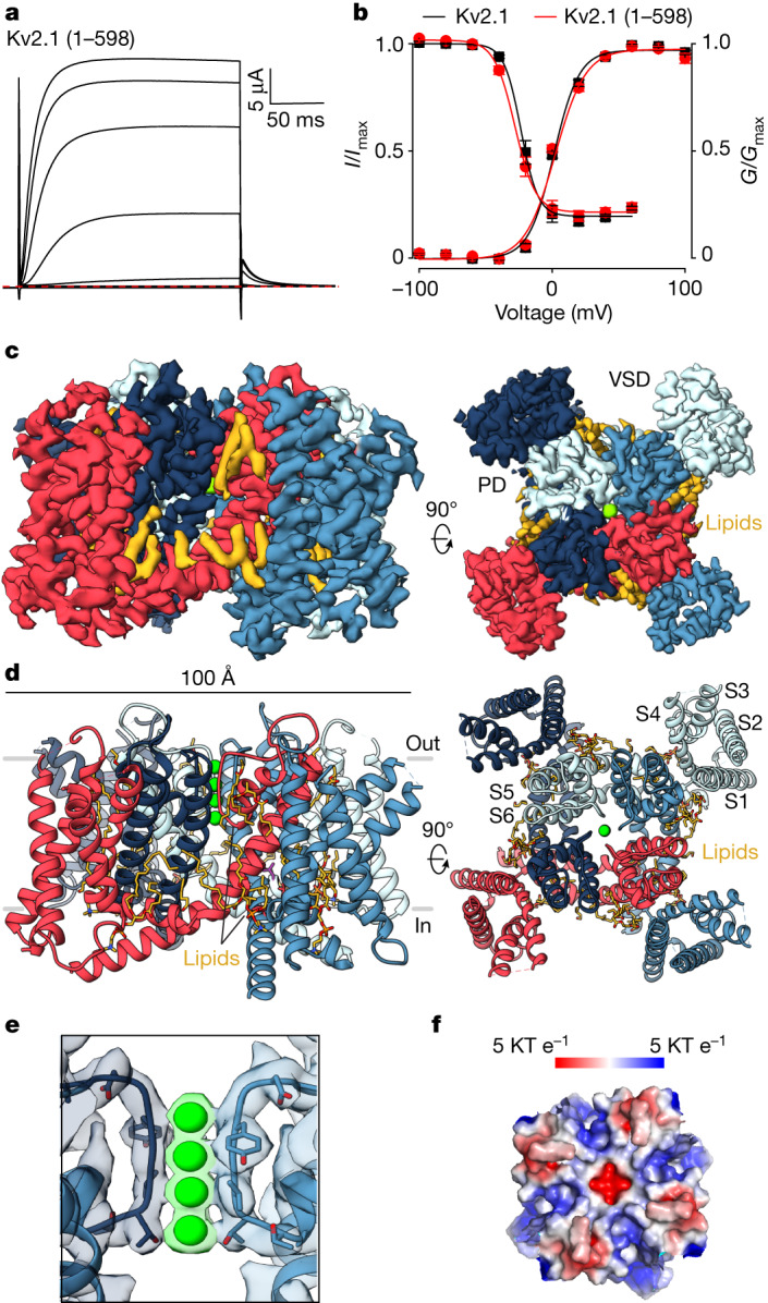
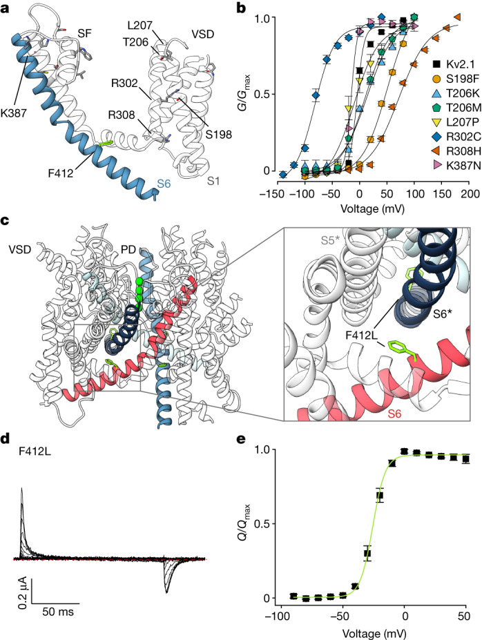
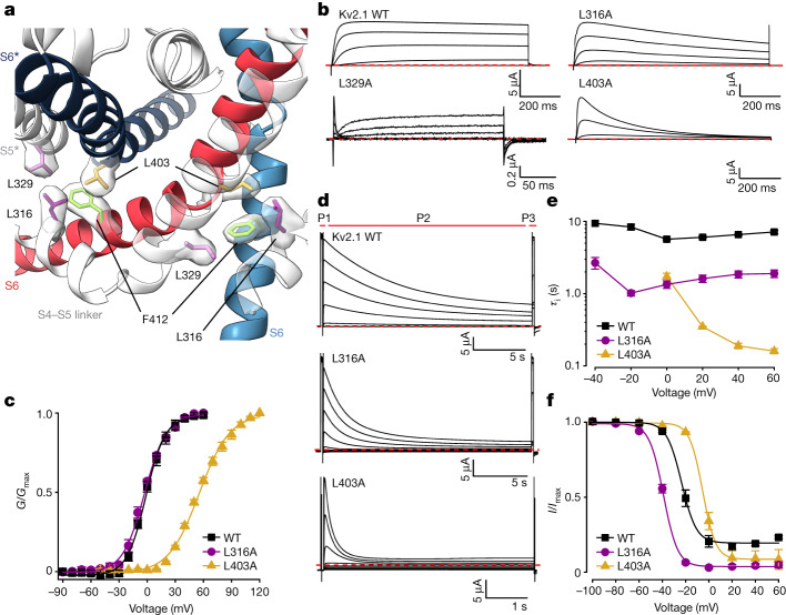
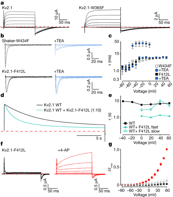
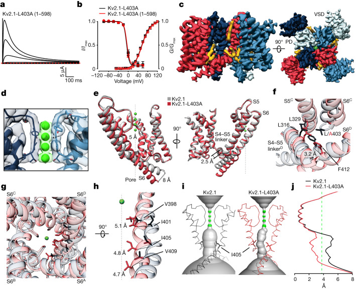
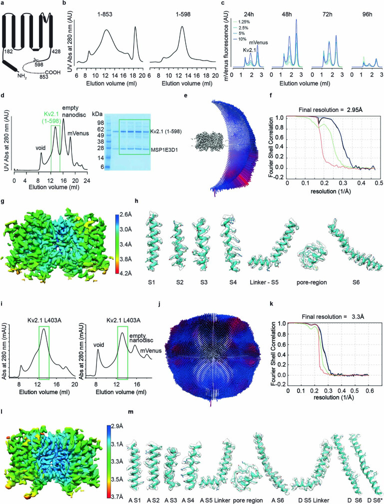
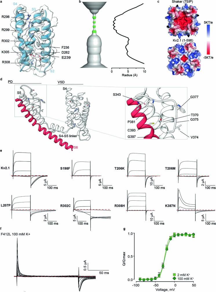
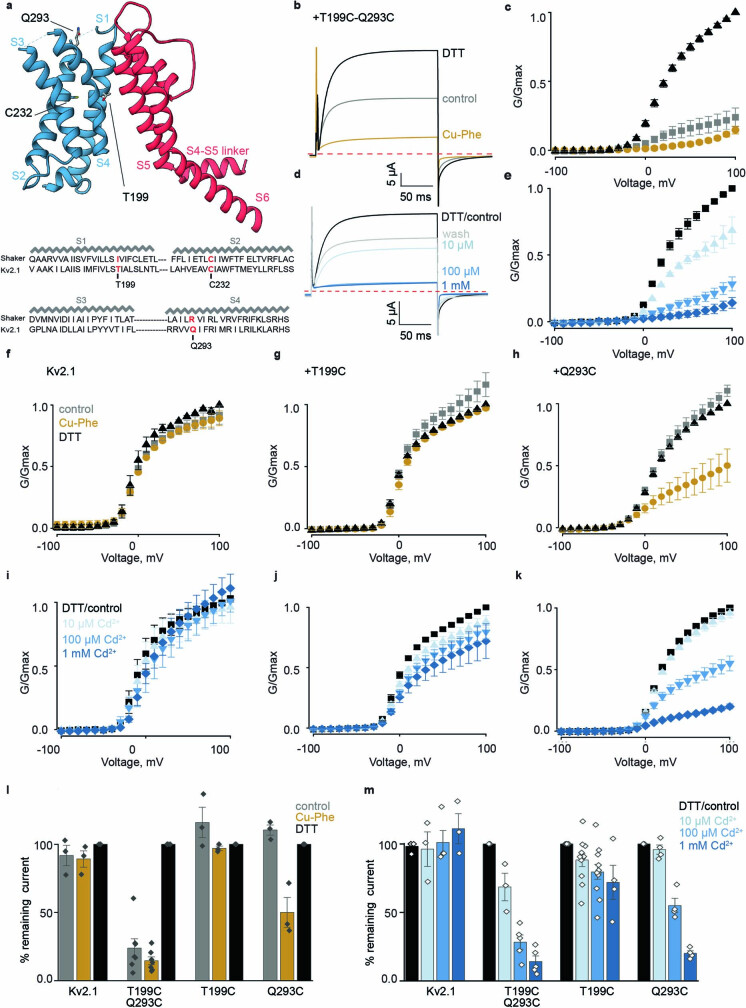
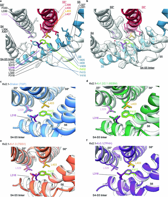
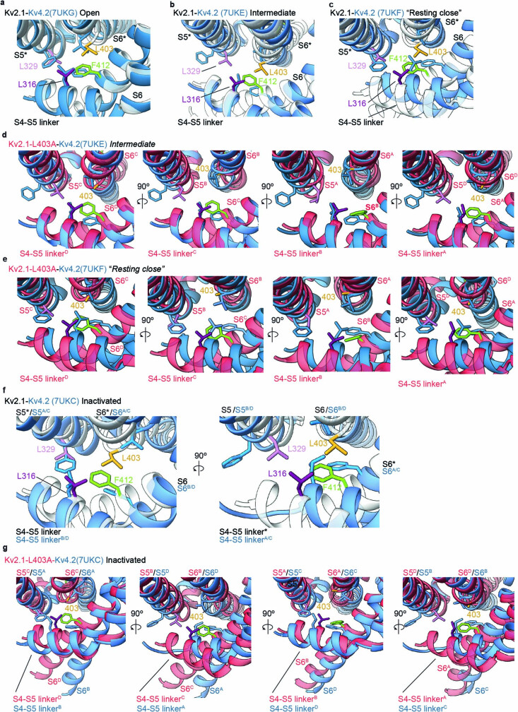
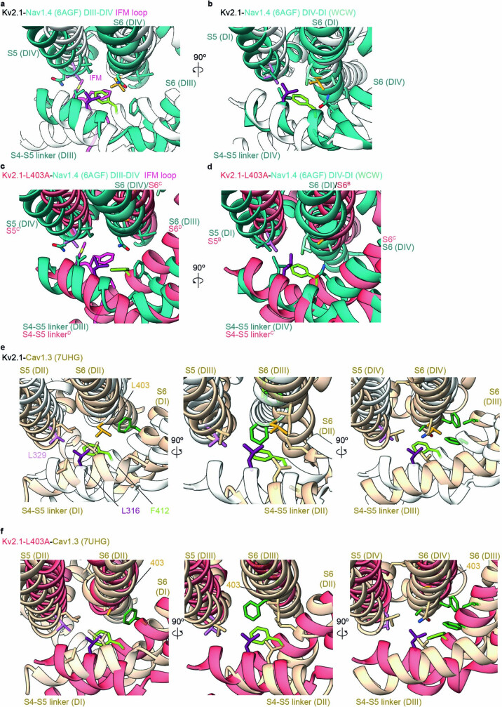
The Kv2.1 voltage-activated potassium (Kv) channel is a prominent delayed-rectifier Kv channel in the mammalian central nervous system, where its mechanisms of activation and inactivation are critical for regulating intrinsic neuronal excitability1,2. Here we present structures of the Kv2.1 channel in a lipid environment using cryo-electron microscopy to provide a framework for exploring its functional mechanisms and how mutations causing epileptic encephalopathies3-7 alter channel activity. By studying a series of disease-causing mutations, we identified one that illuminates a hydrophobic coupling nexus near the internal end of the pore that is critical for inactivation. Both functional and structural studies reveal that inactivation in Kv2.1 results from dynamic alterations in electromechanical coupling to reposition pore-lining S6 helices and close the internal pore. Consideration of these findings along with available structures for other Kv channels, as well as voltage-activated sodium and calcium channels, suggests that related mechanisms of inactivation are conserved in voltage-activated cation channels and likely to be engaged by widely used therapeutics to achieve state-dependent regulation of channel activity.


Conflict of interest statement

The authors declare no competing interests.

Figures

Fig. 1
Fig. 1. Structure of the Kv2.1 channel.
a, Current traces for the structural construct of Kv2.1 (1–598) recorded in 2 mM external K+ from −100 mV to +100 mV (40 mV increments) using a holding voltage of −90 mV and a tail voltage of −50 mV. Red dotted line denotes zero current. b, Normalized conductance–voltage (GV) relations obtained using tail currents from traces like those in a and voltage–steady-state inactivation relations curves (IV) obtained from a three-pulse protocol (Fig. 3d) comparing the structural construct (GV, V1/2 = 1.3 ± 1.2 mV, z =2.7 ± 0.2, n = 6 cells in two independent experiments; IV (inactivation), V1/2 = −27.8 ± 0.9, z = 3.2 ± 0.1, n = 6 cells in two independent experiments) with the full-length Kv2.1 channel (GV, V1/2 = 0.8 ± 1.8 mV, z = 2.8 ± 0.4, n = 10 cells in eight independent experiments; IV (inactivation), V1/2 = −23.3 ± 1.0, z = 3.9 ± 0.3, n = 3 cells in independent experiments). Solid symbols represent mean and solid lines corresponds to fits of the Boltzmann Equations. Error bars denote the standard error of the mean (s.e.m.). c,d, Side and external views of the Kv2.1 EM map (c) and model (d), with each subunit shown in different colours. EM densities that could correspond to lipids are in yellow. e, Close-up view of the selectivity filter model superimposed with the EM map with the K+ ion densities highlighted in green. f, Top view of the electrostatic surface of the extracellular PD of Kv2.1.
Fig. 2
Fig. 2. Epileptic encephalopathy mutations in Kv2.1.
a, Mutations causing epileptic encephalopathy in humans mapped onto one monomer of Kv2.1, shown as a side view. b, GV relations recorded for epileptic encephalopathy mutations highlighted in a and obtained from a family of voltage steps ranging from −150 to +200 mV in 100 mM external K+. Symbols represent mean and solid curves correspond to a fit of the Boltzmann equation. See Extended Data Fig. 2e for traces and Supplementary Table 1 for parameters of the fits and n values. c, Location of F412 in the Kv2.1 structure with adjacent S6 helices highlighted with different colours. d, Gating currents recorded for the F412L epileptic encephalopathy mutation from −90 mV to +50 mV in 2 mM external K+ (10 mV increments) from a holding voltage of −90 mV using a P/−4 protocol to subtract leak and capacitive currents. Red dotted line denotes zero current. e, Normalized QV relation obtained for F412L by integrating the OFF gating currents. Symbols represent mean and green solid curve corresponds to a fit of the Boltzmann Equation with V1/2 = −25.2 ± 0.4 mV, z = 4.4 ± 0.2 (n = 4 cells in two independent experiments). For all panels error bars are s.e.m.
Fig. 3
Fig. 3. A nexus of hydrophobic residues around F412 that are critical for inactivation.
a, A nexus of hydrophobic residues around F412 in the Kv2.1 structure with cryo-EM density for hydrophobic side chains. b, Current traces obtained for Kv2.1, L316A, L403A and L329A using 2 mM external K+ and P/−4 subtraction. Holding voltage was −90 mV, steps were from −90 mV to +60 mV (+50 mV for L329A) in 20 mV increments and tail voltage was −50 mV (−90 mV for L329A). c, GV relations obtained from tail currents for Kv2.1 (n = 13 cells in 10 independent experiments), L316A (n = 3 cells in two independent experiments) and L403A (n = 5 cells in two independent experiments) using 2 mM external K+. Holding voltage was −90 mV, voltage steps were 200 ms and tail voltage was −50 and −60 mV for Kv2.1 and L316A, respectively. For L403A, voltage steps were 20 ms and tail voltage was 0 mV. Symbols represent mean and smooth curves are fits of a Boltzmann equation (Kv2.1, V1/2 = −1.7 ± 0.8 mV, z = 2.6 ± 0.1; L316A, V1/2 = −2.9 ± 0.8, z = 2.2 ± 0.1; L403A, V1/2 = 55.9 ± 1.3 mV, z = 1.5 ± 0.1). d, Effect of Kv2.1 mutations on the rate and extent of inactivation assessed using a three-pulse (P1–P3) protocol with 2 mM external K+ and a holding voltage of −100 mV. P1 was to +60 mV (+50 mV for L403A), followed by a brief step to −100 mV, P2 was from −100 to +60 mV for 20 s to allow channels to inactivate, and P3 was to the same voltage as P1 to assess the fraction of inactivated channels. P2 was 5 sec for L403A. e, Plot of time constants of inactivation (τi) against P2 voltage. τ was obtained by fitting a single exponential function to the time course of the test current in P2. Data points are mean for Kv2.1 (black squares; n = 3 cells in two independent experiments), L316A (purple circles; n = 3 cells in two independent experiments) and L403A (yellow triangles; n = 3 cells in three independent experiments). f, Fraction of non-inactivated channels during each P2 voltage step for Kv2.1 (black squares), L316A (purple circles) and L403A (yellow triangles) obtained by measuring the steady-state current at P3 normalized to P1. Same cells as in e. Smooth curves are fits of a Boltzmann equation (Kv2.1, V1/2 = −23.3 ± 1.0, z = 3.9 ± 0.3; L316A, V1/2 = −39.0 ± 0.5, z = 4.1 ± 0.2; L403A, V1/2 = −5.2 ± 0.5, z = 4.5 ± 0.2). For all panels error bars are s.e.m.
Fig. 4
Fig. 4. Status of the internal gate in the F412L mutant of Kv2.1.
a, Current traces for Kv2.1 (left) and W365F (right). The holding voltage was −90 mV, depolarizations were from −100 to +100 mV (20 mV increments) and tail voltage was −50 mV. External K+ was 100 mM. Red dotted line denotes zero current. b, OFF gating currents recorded for Shaker W434F and Kv2.1 F412L in control (black) or after application of internal TEA (blue) using P/−4 subtraction and 2 mM external K+. The holding voltage for Shaker W434F was −100 mV, test depolarizations were from −100  to 0 mV (10 mV increments). For Kv2.1 F412L the holding voltage was −90 mV, test depolarizations were from −90 to +50 mV (10 mV increments). c, Time constants (τ) for single exponential fits of the decay of OFF gating current in the absence or presence of internal TEA for Shaker W434F (n = 5 cells in five independent experiments) and Kv2.1 F412L (n = 5 cells in five independent experiments). d, Normalized ionic currents recorded for co-expression of Kv2.1 and the Kv2.1-F412L mutant with 2 mM external K+ at 60 mV. e, Plot of time constants (τi) of inactivation against test voltage. τ values were obtained by fitting single (Kv2.1) or double (Kv2.1+Kv2.1-F412L) exponential functions to the time course of the test current in d. Data points are mean for Kv2.1 (black squares; n = 3 cells in two independent experiments) and Kv2.1+Kv2.1-F412L (green triangles; n = 4 cells in two independent experiments). f, Current traces recorded for Kv2.1 F412L before and during application of 10 mM external 4-AP. External K+ was 2 mM. Holding voltage was −90 mV, test depolarizations (200 ms) were from −90 to +60 mV (10 mV increments). g, Normalized steady-state current–voltage (IV) relations for Kv2.1 F412L in control (black squares, n = 6 cells in two independent experiments), in 4-AP (red circles, n = 6 cells in two independent experiments) or after removal of 4-AP (grey squares, n = 3 cells in two independent experiments). Currents were measured at the end of the test depolarization and normalized to the maximum value obtained in the presence of 4-AP. For all panels error bars are s.e.m.
Fig. 5
Fig. 5. Structural basis of inactivation in Kv2.1 channels.
a, Current traces for the structural L403A construct of Kv2.1 (1–598) recorded in 2 mM external K+ from −100 mV to +60 mV (20 mV increments) using a holding voltage of −100 mV. Red dotted line denotes zero current. b, Conductance–voltage (GV) relations and voltage–steady-state inactivation relations (IV) obtained from a three-pulse protocol (Fig. 3d) comparing the L403A Kv2.1 (1–598) (GV, V1/2 = 56.7 ± 1.2 mV, z = 1.5 ± 0.1, n = 5 cells in two independent experiments; IV (inactivation), V1/2 = −6.9 ± 0.7, z = 4.6 ± 0.1, n = 7 cells in two independent experiments) with the L403A mutant in the full-length Kv2.1 channel (Fig. 3c,f). GV relations were obtained from tail currents using a holding voltage of −90 mV, 20 ms voltage steps to between −50 mV and +120 mV (10 mV increments) and a tail voltage of 0 mV. Solid symbols represent mean and solid lines corresponds to fits of the Boltzmann equation. Error bars are s.e.m. c, Side (left) and external (right) views of the Kv2.1-L403A EM map, with each subunit shown in different colours. EM densities that could correspond to lipids are in yellow. d, Model of the ion selectivity filter superimposed with the EM map, with the K+ ion densities highlighted in green. e, Superimposition of the most inactivated subunit of the L403A mutant (protomer D) with one subunit of Kv2.1 illustrating conformational changes in S6, S5 and the S4–S5 linker. f, Conformational changes in the hydrophobic coupling nexus between Kv2.1 and the L403A mutant protomer D. g, Superimposition of Kv2.1 and the L403 mutant structures viewed from the intracellular side of the membrane with key residues in S6 shown in stick representation. h, Superimposed views of the S6 helices of Kv2.1 and the most inactivated subunit (protomer D) of the L403A mutant. i, HOLE representations of the ion permeation pathway for Kv2.1 and the L403A mutant with the backbone for S6 and the selectivity filter of the models shown for reference. j, Plot of pore radius along the ion permeation pathway with dashed green line at the radius of a hydrated K+ ion.
Extended Data Fig. 1
Extended Data Fig. 1. Biochemistry and cryo-EM imaging for the Kv2.1 channel.
a) Cartoon illustrating the Kv2.1 construct used for structure determination. b) Gel filtration chromatograms for the full-length Kv2.1 channel (1-853) and the 1-598 C-terminal truncated construct in detergent solutions using a superose6 increase (10/300) column. The full-length construct showed a broader peak, suggesting heterogeneity of the protein. c) Time-course for expression of the Kv2.1 (1-598) construct in tsA201 transduced with different baculoviruses titers (indicated as %) using mVenus fluorescence in gel filtration chromatograms (superose6 increase 5/150 column) to measure expression. d) Gel filtration profile (Superose6 increase; 10/300 column) for the Kv2.1 (1-598) construct after nanodisc reconstitution. Similar profiles were observed in over 7 independent experiments. The peak in the green box was collected and concentrated for preparing cryo-EM samples. SDS-PAGE analysis of the Kv2.1 (1-598) sample used for cryo-EM data collection. See Supplementary Information Fig. 4 for uncropped gel. e) Direction distribution plots of the 3D reconstruction illustrating the distribution of particles in different orientations with red indicating a larger number of particles. f) Fourier Shell Correlation (FSC) curves: green: rln FSC Unmasked Maps; blue: rln FSC Masked Maps; black: rln FSC Corrected; red: rln FSC Phase Randomized Masked Maps. g) Local resolution map for the entire TM region. h) Regional cryo-EM density for the TM regions of Kv2.1 (1-598). i) Gel filtration chromatograms for the L403A mutant of the 1-598 C-terminal truncated construct in detergent solutions (left). Superose6 increase (10/300) column was used for separation. The peak in the green box was collected and used for nanodisc reconstitution. Gel filtration profile (right; Superose6 increase; 10/300 column) for the L403A mutant of Kv2.1 (1-598) after nanodisc reconstitution. The peak in the green box was collected and concentrated for preparing cryo-EM samples. Similar profiles were observed in over 3 independent experiments. j) Direction distribution plots of the 3D reconstruction illustrating the distribution of particles in different orientations with red indicating a larger number of particles. k) Fourier Shell Correlation (FSC) curves: green: rln FSC Unmasked Maps; blue: rln FSC Masked Maps; black: rln FSC Corrected; red: rln FSC Phase Randomized Masked Maps. l) Local resolution map for the entire TM region. m) Regional cryo-EM density for the TM regions of the L403A mutant of Kv2.1 (1-598). The conformation of the A chain is similar to the activated/open conformation of Kv2.1 while that of the D chain is the most inactivated conformation of the mutant. D S6 shows masked cryo-EM density fitted with the model and D S6* shows unmasked cryo-EM density fitted with the model to further confirm that the trace of the backbone is correct.
Extended Data Fig. 2
Extended Data Fig. 2. Conformation of the Kv2.1 structure and functional properties of epileptic encephalopathy mutations.
a) Side view of the model and EM maps for the S2, S3 and S4 helices within the VSD of Kv2.1. Basic residues in S4 and residues in the charge transfer center (F236, E239 and D262) are shown as sticks. b) Hole representation of the ion permeation pathway of the Kv2.1 structure and plot of pore radius along the length of the pore. c) View of the electrostatic surface of the extracellular PD of the Shaker channel (PDB 7SIP) and Kv2.1 (1-598). d) Side view of a single monomer of Kv2.1 with epileptic encephalopathy mutations shown in stick representation. Regions contributing to the PD and VSD are indicated and an expanded view of the PD is also shown. e) Current traces obtained with 100 mM extracellular K+ from cells expressing mutant Kv2.1 channels. For WT Kv2.1, S198F, T206K, T206M, L207P and K387N mutants, steps were from −100 mV to +100 mV in 40 mV increments, holding voltage was −90 mV and tail voltage was −50 mV. R302C currents were recorded using a protocol with a holding voltage of −120 mV, using a pre-pulse to −140 mV followed by a family of voltage steps from −140 mV to +80 mV in 40 mV increments and a tail voltage of −100 mV. R308H currents were recorded using a holding voltage of −90 mV, steps from −100 mV to +180 mV in 40 mV increments and a tail voltage of −50 mV. Red dotted line denotes zero current. f) Gating currents recorded for Kv2.1 F412L in the presence of 100 mM external K+. Holding voltage was −90 mV, steps were from −90 mV to +50 mV (10 mV increments) and a P/−4 protocol was used to subtract the leak and the capacitive currents. g) Q-V relations for the F412L mutant in 2- and 100-mM external K+. Data for low K+ are from Fig. 2d, e. Symbols represent mean, error bars represent S.E.M. and dark green solid curve is a fit of the Boltzmann Equation to data in high K+ with V1/2 = −24.8 ± 0.5 mV, z = 3.7 ± 0.3 (n = 3 cells in 3 independent experiments).
Extended Data Fig. 3
Extended Data Fig. 3. Gauging the movements of S4 in Kv2.1 (1-598) with disulfide and metal bridges.
a) Side view of the VSD of one subunit (blue) and the PD of the adjacent subunit (red). Q293 in the R1 position of S4, T199 in the S1 helix and C232 in the S2 helix are shown as sticks. Sequence alignment shows the TM segments within the VSDs of Shaker and Kv2.1. b) Superimposed traces obtained from the same oocyte expressing the T199C/Q293C double mutant of Kv2.1 treated as indicated. Holding voltage was −90 mV, test voltage was +100 mV, tail voltage was −50 mV and external K+ was 50 mM. The control (gray) trace was obtained before any treatment, the Cu-Phe trace (dark yellow) in presence of Cu-Phe (1.5 µM–5 µM) and the DTT trace (black) after incubation with DTT (10 mM) for 10 min. c) G-V relations obtained for cells treated as in b using tail current measurements (-50 mV) and normalizing to the maximal current amplitude after DTT treatment (n = 7 cells in 2 independent experiments). d) Superimposed traces obtained from the same oocyte expressing the T199C/Q293C double mutant of Kv2.1 treated as indicated. Holding voltage was −90 mV, test voltage was +100 mV, tail voltage was −50 mV and external K+ was 50 mM. The control (black) trace was obtained after incubation with DTT (10 mM) for 10 min before applying Cd2+ at the indicated concentrations (blue traces) and then returning to control external solution (gray trace). e) G-V relations obtained for cells treated as in d using from tail current measurements (−50 mV) and normalized to the maximal current amplitude after DTT treatment (n = 5 cells in 2 independent experiments for control, 100 µM and 1 mM Cd2+ and n = 3 cells in 2 independent experiments for 10 µM Cd2+). f) G-V relations obtained for cells expressing WT Kv2.1 and treated as in b using tail current measurements (−50 mV) and normalizing to the maximal current amplitude after DTT treatment (n = 3 cells in 2 independent experiments). g) G-V relations obtained for cells expressing T199C and treated as in b using tail current measurements (n = 3 cells in 2 independent experiments). h) G-V relations obtained for cells expressing Kv2.1 Q239C and treated as in b using tail current measurements (n = 3 cells in 2 independent experiments). i) G-V relations obtained for cells expressing Kv2.1 WT and treated as in d using tail current measurements (−50 mV) and normalizing to the maximal current amplitude after DTT treatment (n = 4 cells in 2 independent experiments for control and 100 µM Cd2+ and n = 3 cells in 2 independent experiments for both 10 µM and 1 mM Cd2+). j) G-V relations obtained for cells expressing Kv2.1 T199C and treated as in d using tail current measurements (n = 11 cells in 4 independent experiments for control, 10 µM and 100 µM Cd2+ and n = 4 cells in 4 independent experiments for 1 mM Cd2+). k) G-V relations obtained for cells expressing Kv2.1 Q293C and treated as in d using tail current measurements (n = 4 in 2 independent experiments). l) Quantification of the effects of oxidizing (Cu-Phe) and reducing (DTT) conditions for a population of cells treated similarly to that in b. Currents were first elicited in control condition without any treatments and then after treated with Cu-Phe followed by DTT. Steady-state current at the end of test pulses to +100 mV were normalized to the maximal current amplitude after DTT treatment for the different constructs tested: Kv2.1 (n = 3 in 2 independent experiments), Kv2.1 T199C-Q239C (n = 7 in 2 independent experiments), Kv2.1 T199C (n = 3 in 2 independent experiments), Kv2.1 Q239C (n = 3 in 2 independent experiments). m) Quantification of the effect of Cd2+ at the concentrations indicated by measuring the steady-state current at +100 mV and normalizing it by the current measured after DTT incubation for the different constructs tested: Kv2.1 (n = 4 cells in 2 independent experiments for control, n = 3 in 2 independent experiments for 10 µM Cd2+, n = 4 in 2 independent experiments for 100 µM Cd2+ and n = 3 cells in 2 independent experiments for 1 mM Cd2+), Kv2.1 T199C-Q239C (n = 5 cells in 2 independent experiments for control, 100 µM and 1 mM Cd2+ and n = 3 in 2 independent experiments for 10 µM Cd2+), Kv2.1 T199C (n = 11 cells in 4 independent experiments for control, 10 µM and 100 µM Cd2+, and n = 4 cells in 4 independent experiments for 1 mM Cd2+), and Kv2.1 Q239C (n = 4 cells in 2 independent experiments for control and all Cd2+ concentrations. In all panels error bars represent S.E.M. All experiments in this figure were with the structural construct: Kv2.1 (1-598).
Extended Data Fig. 4
Extended Data Fig. 4. Exploring the non-conducting mechanism for Kv2.1 F412L.
a) Close up view of the model and EM map for D378 in the P-loop and W365 in the pore helix. Dashed line represents a hydrogen bond. b) Fraction of non-inactivated channels (P3/P1) in response to the P2 family of voltage steps from −100 to +60 mV for Kv2.1 (black squares; n = 3 in 2 independent experiments) and the W365F mutation (orange circles; n = 5 in 2 independent experiments). Similar protocol to that illustrated in Fig. 3d. External K+ was 2 mM. c) Fraction of non-inactivated channels for Kv2.1 W365F recorded in 2 or 100 mM external K+ using P/−4 subtraction. Coloured diamonds denote individual experiments (n = 8 cells in 2 independent experiments for 2 mM K+ and n = 6 in 2 independent experiments for 100 mM K+) and solid black diamonds represent mean. d) Family of current traces for Kv2.1 with 2 mM external K+ in the absence and presence of internal TEA. Test depolarizations were from −100 to +50 mV in 10 mV increments from a holding voltage of −90 mV using P/−4 subtraction. Insets show tail currents recorded at –50 mV. Red line indicates zero current. e) Plot of time constant of deactivation for Kv2.1 in the absence and presence of internal TEA (n = 3 in 2 independent experiments). f) Family of current traces for Kv2.1 L329A with 2 mM external K+ in the absence and presence of internal TEA. Test depolarizations were from −90 to +50 mV in 10 mV increments with holding and tail voltages of −90 mV using P/−4 subtraction. Red line indicates zero current. g) Plot of time constant of slow current measured for Kv2.1 L329A upon repolarization in the absence and presence of internal TEA (n = 7 in 4 independent experiments). h) Current families for Kv2.1 obtained using a three-pulse protocol with 2 mM external K+ and a holding voltage of −100 mV. The first pulse (P1) was to +60 mV, followed by a brief closure to −100 mV, the test pulse (P2) was from −100 to +60 mV for 20 s to allow the channels to inactivate, and a third pulse (P3) to the same voltage than P1 to assess the fraction of inactivated channels i) Plot of time constants (τ) of inactivation against P2 voltage. τ was obtained by fitting a single or double exponential function to the time course of the test current in P2. Data points are mean and error bars are S.E.M. for Kv2.1 (black squares; n = 3 in 2 independent experiments), Kv2.1+Kv2.1-F412L (1:1) (green circles; n = 3 in 2 independent experiments) and Kv2.1+Kv2.1-F412L (1:10) (green triangles; n = 4 in 2 independent experiments). j) Current families obtained as in h but when co-expressing Kv2.1 with the F412L mutant using a 1:1 molar ratio of cRNA. k) Amplitudes for the fast and slow components of the double-exponential fits obtained when co-expressing Kv2.1 with F412L. Same cells and n values as panel i. l) Current families obtained as in h but when co-expressing Kv2.1 with the F412L mutant using a 1:10 molar ratio of cRNA. m) Plot of fraction of non-inactivated channels during each P2 voltage step for Kv2.1 (black squares; n = 3 in 2 independent experiments), Kv2.1+Kv2.1-F412L (1:1) (green circles; n = 6 in 2 independent experiments) and Kv2.1+Kv2.1-F412L (1:10) (green triangles; n = 6 in 2 independent experiments) obtained by measuring the steady-state current at P3 normalized to P1. Smooth curves are fits of a Boltzmann equation (Kv2.1, V1/2 = −23.3 ± 1.0 mV, z = 3.9 ± 0.3; Kv2.1:F412L 1:1, V1/2 = −30.1 ± 1.4 mV, z = 4.1 ± 0.3; Kv2.1:F412L 1:10, V1/2 = −30.1 ± 2.1 mV, z = 3.6 ± 0.3). For all panels error bars are S.E.M.
Extended Data Fig. 5
Extended Data Fig. 5. 4-AP interferes with inactivation in Kv2.1.
a) Current traces for Kv2.1 with 2 mM external K+ in the absence and presence of 4-AP (10 mM). Test depolarizations were from −90 to +60 mV in 20 mV increments from a holding voltage of −90 mV using a tail voltage of −60 mV and P/−4 subtraction. Red and black dashed lines indicates zero current. b) G-V relations obtained measuring the peak tail currents from traces as shown in panel a for Kv2.1 (n = 3 in 2 independent experiments) before and after 4-AP addition. Tail currents were normalized to the maximum value in control solution. c) G-V relations independently normalized to the maximum tail current amplitude recorded in the absence or presence of 4-AP. Fits of the Boltzmann equation to the data are shown as solid curves. For control, V1/2 = −1.1 ± 0.9 mV and z = 2.4 ± 0.1 For 4-AP, V1/2 = 18.1 ± 0.9 mV and z = 2.1 ± 0.1. Same cells as in panel b. d) Current families for Kv2.1 obtained using a three-pulse protocol with 2 mM external K+ in the presence of 4-AP (10 mM). Holding voltage of −100 mV, the first pulse (P1) was to +60 mV, followed by a brief closure to −100 mV, the test pulse (P2) was from −100 to +60 mV for 20 s to allow the channels to inactivate, and a third pulse (P3) to +60 mV to assess the fraction of inactivated channels. Black dashed line indicates zero current. See Fig. 3d for control traces in the absence of 4-AP. e) Plot of fraction of non-inactivated channels during the P2 voltage step (P3/P1) for Kv2.1 in control solution (black squares) and after application of 4-AP (red squares). Current amplitudes in 4-AP were normalized to that in control in the same cell. Data points are mean and n = 3 in 2 independent experiments. Solid line in control is a fit of a Boltzmann equation to the control data with V1/2 = −23.3 ± 1.0 mV, z = 3.9 ± 0.3. f) Time constants for inactivation for Kv2.1 in control solution and in the presence of 4-AP (10 mM). Values for τ were obtained by fitting a single exponential function to the time course of current decay during P2 in panel d. Inactivation is barely detectable on this timescale in the presence of 4-AP and thus τ values in that condition are poorly defined. Same cells as in panel e. g) Current families for Kv2.1 L316A obtained using a three-pulse protocol with 2 mM external K+ in the presence of 4-AP (10 mM). Same protocol as in d. Dashed black line indicates zero current. See Fig. 3d for control traces in the absence of 4-AP. h) Plot of fraction of non-inactivated channels during the P2 voltage step (P3/P1) for Kv2.1 L316A in control solution (purple circles) and after application of 4-AP (red circles). Current amplitudes in 4-AP were normalized to that in control in the same cell. Data points are mean and n = 3 in 2 independent experiments. Solid line in control is a fit of a Boltzmann equation to the data with V1/2 = −39.0 ± 0.5 mV and z = 4.3 ± 0.2. i) Time constants for inactivation for Kv2.1 L316A in control solution and in the presence of 4-AP (10 mM). Values for τ were obtained by fitting a single exponential function to the time course of current decay during P2 in panel g. Same cells as in panel h. j) Current families for Kv2.1 L403A obtained using a three-pulse protocol with 2 mM external K+ in the presence of 4-AP (10 mM). Similar protocol to that in d except P1 and P3 were to +50 mV and P2 duration was 5 sec. Dashed black line indicates zero current. See Fig. 3d for control traces in the absence of 4-AP. k) Plot of fraction of non-inactivated channels during the P2 voltage step (P3/P1) for Kv2.1 L403A in control solution (yellow triangles) and after application of 4-AP (red triangles). Current amplitudes in 4-AP were scaled to that in control in the same cell. Data points are mean and n = 4 in 4 independent experiments. Solid line is a fit of a Boltzmann equation to the data with V1/2 = −4.9 ± 0.8 mV and z = 4.3 ± 0.3. l) Time constants for inactivation for Kv2.1 L403A in control solution and in the presence of 4-AP (10 mM). Values for τ were obtained by fitting a single exponential function to the time course of current decay during P2. Same cells as in panel k. Bar graph insert represents the mean % of remaining current at the end of the trace measured before (yellow) and after 4-AP (red). Symbols represent individual experiments and error bars are S.E.M.
Extended Data Fig. 6
Extended Data Fig. 6. Structural comparison of Kv2.1 and the L403A mutant.
a) Superimposition of Kv2.1 (gray) with each of the four protomers of the L403A mutant aligned using the VSDs. b) Cryo-EM map of a single subunit of Kv2.1 (gray) with the map for protomer D in the L403A mutant (red). c) Conformational changes at the interface between S5 and S6 helices between Kv2.1 (gray) and protomer D of the L403A mutant (red). d) Conformational changes in the S6 helix between Kv2.1 (gray) and protomer D of the L403A mutant (red). Cryo-EM maps for S6 helices from protomer D in the L403A mutant (red) and Kv2.1 (gray) are shown to the right. e,f) A symmetrical L403A tetramer generated by aligning four D protomers to Kv2.1 based on selectivity filter. Dash lines indicate clashes between neighboring I405 side chains (e), between the sidechain of L329 and backbone of G312 (f) and between the sidechain of F333 and that of L313 (f). g,h) A symmetrical L403A tetramer modeled by aligning four D protomers to Kv2.1 based on the VSDs. Dash lines show clashes between neighboring I405 side chains (g) and distances between backbone carbonyls within the selectivity filter that are shorter when compared to those of Kv2.1 and other K+ channels whose filters are thought to be conducting (h).
Extended Data Fig. 7
Extended Data Fig. 7. A selectivity filter mutant interferes with inactivation in Kv2.1 L403A.
a) Current traces for the Kv2.1-L403A-T373A double mutant and Kv2.1-T373A with 2 mM external K+. Test depolarizations for Kv2.1-L403A-T373A were from −90 to +60 mV in 10 mV increments from a holding voltage of −90 mV using a tail voltage of −60 mV with P/−4 subtraction. Kv2.1-T373A test depolarizations were from −90 to +50 mV in 10 mV increments from a holding voltage of −90 mV using a tail voltage of −70 mV. Red line indicates zero current. b) G-V relations obtained by measuring the peak tail currents from traces as shown in panel a for Kv2.1- T373A (blue circles, n = 6 in 4 independent experiments) and Kv2.1- L403A-T373A (inverted maroon triangles, n = 6 in 4 independent experiments). For comparison purposes, data for L403A and Kv2.1 are also shown from Fig. 3c. Symbols represent mean and solid line is a fit of a Boltzmann equation to the data for Kv2.1-T373A (V1/2 = −38.4 ± 1.5 mV and z = 3.4 ± 0.4), Kv2.1-T373A-L403A (V1/2 = −25.1 ± 1.8 mV and z = 1.9 ± 0.1). c) Plot of fraction of non-inactivated during the P2 voltage step (P3/P1) using the same protocol as in Fig. 3d for Kv2.1-T373A-L403A (inverted maroon triangles, n = 4 in 2 independent experiments) in 2 mM external K+. Kv2.1 and Kv2.1-L403A are shown from comparison purposes (from Fig. 3f). d) Side views of the Kv2.1 model for two neighboring subunits, from the S4-S5 linker to the S6 (S6 coloured in dark blue or red). Residues tested in the present manuscript that modify inactivation are shown in different colours. Other residues that undergo rearrangements during inactivation as seen in the Kv2.1-L403A model (see Fig. 5, Extended Data Fig. 6) are shown in the same colour as the helix. For all panels error bars are S.E.M.
Extended Data Fig. 8
Extended Data Fig. 8. Additional hydrophobic residues interacting with the hydrophobic coupling nexus in Kv2.1 and structural alignment of Kv2.1 with other Kv channels.
a) View of the hydrophobic coupling nexus residues highlighted with the side chains depicted as sticks with F412 green, L316 purple, L329 light purple and L403 yellow, with additional hydrophobic residues depicted as sticks coloured based on the helix in which they are located. b) Same view and model as in panel a but also showing cryo-EM density for hydrophobic side chains. c-f) Close-up view of the hydrophobic coupling nexus residues highlighted with the side chains depicted as sticks with Kv2.1 residues labeled for Kv2.1 (white) and c) Shaker-IR (blue), d) Kv1.2/2.1 paddle chimera (green), e) Kv1.3 (orange) and f) Kv3.1 (purple).
Extended Data Fig. 9
Extended Data Fig. 9. Structural alignment of Kv2.1 and Kv4.2 channels proposed to be in open, intermediate, resting/close or inactivated states.
a) Close-up view of the hydrophobic coupling nexus residues in Kv2.1 (white) and an open state of Kv4.2 (blue). b) Hydrophobic coupling nexus residues in Kv2.1 (white) and an intermediate state of Kv4.2 (blue). c) Hydrophobic coupling nexus residues in Kv2.1 (white) and a resting/close state of Kv4.2 (blue). d) Hydrophobic coupling nexus residues in the four protomers of the L403A mutant of Kv2.1 (red) and an intermediate state of Kv4.2 (blue). e) Hydrophobic coupling nexus residues in the four protomers of the L403A mutant of Kv2.1 (red) and a resting/close state of Kv4.2 (blue). f) Close-up view of the hydrophobic coupling nexus residues in Kv2.1 (white) and the two distinct protomers present in an inactivated state of Kv4.2 (blue). g) Hydrophobic coupling nexus residues in the four protomers of the L403A mutant of Kv2.1 (red) and the two distinct protomers present in an inactivated state of Kv4.2 (blue).
Extended Data Fig. 10
Extended Data Fig. 10. Structural alignment of Kv2.1 with Nav1.4 and Cav1.3 channels.
a) Close-up view of the hydrophobic coupling nexus residues in Kv2.1 (white) and between domains III and IV of Nav1.4 (blue). b) Hydrophobic coupling nexus residues in Kv2.1 (white) and between domains IV and I of Nav1.4 (blue). WCW mutants (see Discussion) are shown in stick representation (light blue). c) Hydrophobic coupling nexus residues in the L403A mutant of Kv2.1 (red) and between domains III and IV of Nav1.4 (blue). d) Hydrophobic coupling nexus residues in the L403A mutant of Kv2.1 (red) and between domains IV and I of Nav1.4 (blue). e,f) Close-up view of the hydrophobic coupling nexus residues highlighted with the side chains depicted as sticks with Kv2.1 residues labeled for Kv2.1 (white) and Cav1.3 (tan) (e) or Kv2.1-L403A (red) and Cav1.3 (tan) (f). Dark green side chains identify residues where mutations enhance voltage dependent inactivation.

Similar articles

Cited by

References

    1. Misonou H, Mohapatra DP, Trimmer JS. Kv2.1: a voltage-gated K+ channel critical to dynamic control of neuronal excitability. Neurotoxicology. 2005;26:743–752. doi: 10.1016/j.neuro.2005.02.003. - DOI - PubMed
    1. Liu PW, Bean BP. Kv2 channel regulation of action potential repolarization and firing patterns in superior cervical ganglion neurons and hippocampal CA1 pyramidal neurons. J. Neurosci. 2014;34:4991–5002. doi: 10.1523/JNEUROSCI.1925-13.2014. - DOI - PMC - PubMed
    1. Thiffault I, et al. A novel epileptic encephalopathy mutation in KCNB1 disrupts Kv2.1 ion selectivity, expression, and localization. J. Gen. Physiol. 2015;146:399–410. doi: 10.1085/jgp.201511444. - DOI - PMC - PubMed
    1. Torkamani A, et al. De novo KCNB1 mutations in epileptic encephalopathy. Ann. Neurol. 2014;76:529–540. doi: 10.1002/ana.24263. - DOI - PMC - PubMed
    1. Kang SK, et al. Spectrum of K(V) 2.1 dysfunction in KCNB1-associated neurodevelopmental disorders. Ann. Neurol. 2019;86:899–912. doi: 10.1002/ana.25607. - DOI - PMC - PubMed

MeSH terms

Substances

LinkOut - more resources