Review
. 2023 Sep 11;16(18):6158.
doi: 10.3390/ma16186158.

Zirconium Carbide for Hypersonic Applications, Opportunities and Challenges

Affiliations
Review

Zirconium Carbide for Hypersonic Applications, Opportunities and Challenges

Glenn R Peterson et al. Materials (Basel). .

Abstract

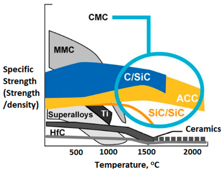
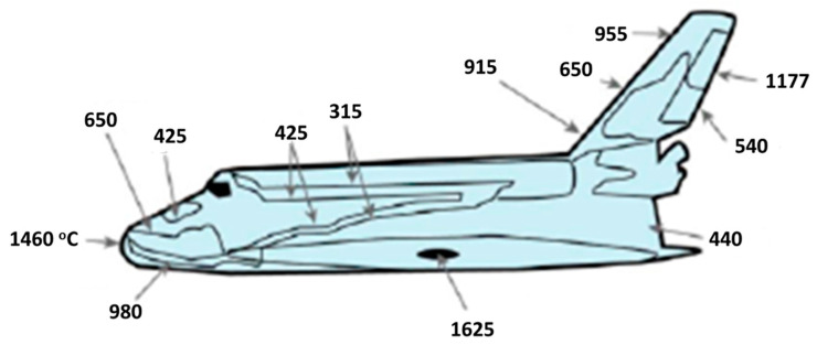
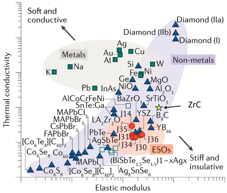
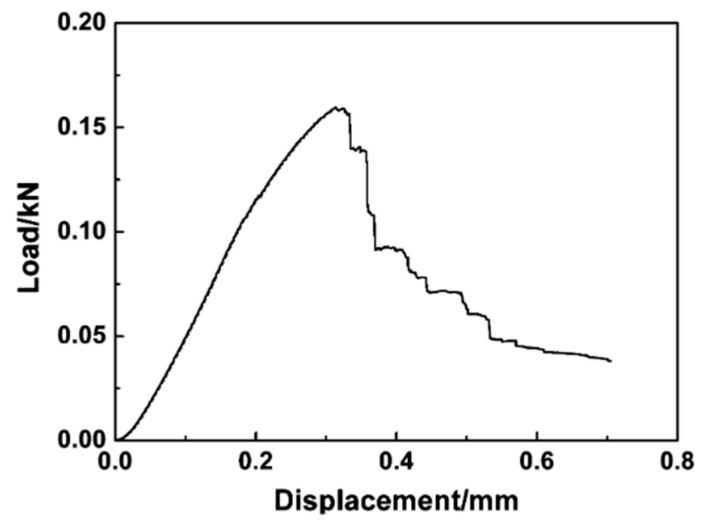
At ultra-high temperatures, resilient, durable, stable material choices are limited. While Carbon/Carbon (C/C) composites (carbon fibers and carbon matrix phases) are currently the materials of choice, zirconium carbide (ZrC) provides an option in hypersonic environments and specifically in wing leading edge (WLE) applications. ZrC also offers an ultra-high melting point (3825 K), robust mechanical properties, better thermal conductivity, and potentially better chemical stability and oxidation resistance than C/C composites. In this review, we discuss the mechanisms behind ZrC mechanical, thermal, and chemical properties and evaluate: (a) mechanical properties: flexure strength, fracture toughness, and elastic modulus; (b) thermal properties: coefficient of thermal expansion (CTE), thermal conductivity, and melting temperature; (c) chemical properties: thermodynamic stability and reaction kinetics of oxidation. For WLE applications, ZrC physical properties require further improvements. We note that materials or processing solutions to increase its relative density through sintering aids can have deleterious effects on oxidation resistance. Therefore, improvements of key ZrC properties for WLE applications must not compromise other functional properties. We suggest that C/C-ZrC composites offer an engineering solution to reduce density (weight) for aerospace applications, improve fracture toughness and the mechanical response, while addressing chemical stability and stoichiometric concerns. Recommendations for future work are also given.

Keywords: ZrC; hypersonics; ultra-high temperature ceramics.


Conflict of interest statement

The authors declare no conflict of interest.

Figures

Figure 1
Figure 1
Zr-C phase diagram [4].
Figure 2
Figure 2
The specific strengths (SE) of various WLE candidate materials at elevated temperatures. Metal Matrix Composites (MMC) have initially high SE, but it rapidly decreases with increasing temperature. Ceramic Matrix Composites (CMC) tend to have stable SE through a wide temperature range. In super alloys such as MMCs and other metals, SE decrease rapidly near the melting point. Advanced C/C Composites (ACC) and C/SiC composites generally exhibit high melting points and low densities and maintain high SE over a wide temperature range. While having a generally lower SE, ceramics can potentially exhibit constant strength. There are some ceramics of interest above 1500 °C, such as ZrC, that have comparable melting points to ACC materials and are mechanically stable [14].
Figure 3
Figure 3
Density Functional Theory Model of ZrC showing a rock salt bonding lacking C-C bonding [4].
Figure 4
Figure 4
Flexure strength vs. temperature (°C) for monolithic ZrC (diamonds) and TaC, ZrC, and NbC alloy—TZN-3 (squares)—adapted from Demirskyi [10]. While the peak strength of TZN-3 is twice that of ZrC, it is not as strong as monolithic ZrC at T > 2000 °C.
Figure 5
Figure 5
Fracture toughness vs. temperature calculated from First Principles Density Functional Theory. As ultra-high temperatures can present challenges, models aid in predicting performance and are useful to predict mechanical behaviors and properties in these extreme environments [38,39].
Figure 6
Figure 6
Nominal surface temperature profile of Space Shuttle Orbiter in degrees Celsius adopted from glass [14].
Figure 7
Figure 7
CTE vs. temperature for ZrC from measured values based on Touloukian’s compilation [15].
Figure 8
Figure 8
CTE vs. temperature for polycrystalline substrate candidates of WC, SiC, and ZrC with potential coating candidates of Y2O3 and MoSi2 are shown. ZrC offers a higher temperature range coupled with better CTE matching to potential coatings of MoSi2 and Y2O3 compared with other ceramics such as WC or SiC, which have a greater CTE mismatch with Y2O3 and MoSi2 [15].
Figure 9
Figure 9
Thermal conductivity of ZrC vs. temperature. While there is considerable variance in measurements as noted by the authors, there is a common trend of increasing thermal conductivity that is atypical of ceramics and is attributed to the metal-like behavior of the Zr-Zr bonds at high temperatures [4].
Figure 10
Figure 10
Gibbs energy of reaction vs. temperature of Zr and nonmetallic species (C, B, N2, and O2) for high-temperature Zr compounds [48].
Figure 11
Figure 11
Oxide Layer Growth on ZrC (Left) at 800 °C for 4 h and (Right) at 1100 °C for 30 min [18].
Figure 12
Figure 12
Oxide scale growth on ZrC from 800 °C to 1100 °C in air [17].
Figure 13
Figure 13
Mass loss due to oxidation vs. time and temperature of C/C composites [19].
Figure 14
Figure 14
Ashby plot of thermal conductivity vs. elastic modulus in log–log scale. The corresponding values for ZrC are shown [51].
Figure 15
Figure 15
Load vs. displacement for Type-B, 3-pt flexure test of C/C–ZrC–ZrB2 showing the effects of forming a composite to prevent abrupt failure as indicative of the cascading failure beyond 0.3 mm [53].
Figure 16
Figure 16
The fracture surface of ZrB2 reinforced with C/C Fibers (a). Evidence of C/C fiber pullout at the fracture surface (b). Fiber fracture (c), EDS results from fiber surface (d) [53].
Figure 17
Figure 17
C/Zr ratio effect on ZrC lattice parameter [3].
Figure 18
Figure 18
(Top) CTE and (Bottom) volumetric change vs. temperature of doped and undoped ZrC [54].
Figure 18
Figure 18
(Top) CTE and (Bottom) volumetric change vs. temperature of doped and undoped ZrC [54].
Figure 19
Figure 19
Example of cracks from thermal processing of C/SiC. Cracks form parallel (Type II) and perpendicular (Type I) to the carbon fiber (a). Debonding between carbon fiber SiC matrix (b) [45].
Figure 20
Figure 20
(Top) Percent weight loss vs. time at 1500 °C and (Bottom) percent weight loss during thermal cycling from room temperature to 1500 °C for ZrB2-SiC/SiC and SiC for graphite-coated specimens. From ZS20 to ZS50, the amount of ZrB2 is decreased, and SiC is increased from 43% to 71%. The coatings with the higher SiC phase fraction performed better. The ZS40 and ZS50 coatings performed similarly at early and late times, but ZS40 performs better at intermediate times. For WLE applications, the hold time is less important than cycling. Lastly, the SiC coating is the weakest performer in both cases [56].
Figure 20
Figure 20
(Top) Percent weight loss vs. time at 1500 °C and (Bottom) percent weight loss during thermal cycling from room temperature to 1500 °C for ZrB2-SiC/SiC and SiC for graphite-coated specimens. From ZS20 to ZS50, the amount of ZrB2 is decreased, and SiC is increased from 43% to 71%. The coatings with the higher SiC phase fraction performed better. The ZS40 and ZS50 coatings performed similarly at early and late times, but ZS40 performs better at intermediate times. For WLE applications, the hold time is less important than cycling. Lastly, the SiC coating is the weakest performer in both cases [56].
Figure 21
Figure 21
Layer formation during coating with SiC-ZrC of SiC [45].
Figure 22
Figure 22
(a) C/SiC-ZrC-Y2O3 coating and (b) C/SiC-ZrC-La2O3 coating ablation mechanism [60].

References

    1. Tenney D.R., Lisagor W.B., Dixon S.C. Materials and Structures for Hypersonic Vehicles. International Council of the Aeronautical Sciences; Hampton, VA, USA: 1988.
    1. Vasile B.S., Birca A.C., Surdu V.A., Neacsu I.A., Nicoară A.I. Ceramic Composite Materials Obtained by Electron-Beam Physical Vapor Deposition Used as Thermal Barriers in the Aerospace Industry. Nanomaterials. 2020;10:370. doi: 10.3390/nano10020370. - DOI - PMC - PubMed
    1. Katoh Y., Vasudevamurthy G., Nozawa T., Snead L.L. Properties of zirconium carbide for nuclear fuel applications. J. Nucl. Mater. 2013;441:718–742. doi: 10.1016/j.jnucmat.2013.05.037. - DOI
    1. Harrison R.W., Lee W.E. Processing and properties of ZrC, ZrN and ZrCN ceramics: A review. Adv. Appl. Ceram. 2016;115:294–307. doi: 10.1179/1743676115Y.0000000061. - DOI
    1. Lanin A.G., Zubarev P.V., Vlasov K.P. Mechanical and Thermophysical Properties of Materials in HTGR Fuel Bundles. Atomic Energy. 1998;74:40–44. doi: 10.1007/BF00750973. - DOI

LinkOut - more resources