Review
. 2023 Sep 11:10:1199067.
doi: 10.3389/fcvm.2023.1199067. eCollection 2023.

The role of intravascular imaging in chronic total occlusion percutaneous coronary intervention

Affiliations
Review

The role of intravascular imaging in chronic total occlusion percutaneous coronary intervention

Iosif Xenogiannis et al. Front Cardiovasc Med. .

Abstract

Chronic total occlusions (CTOs) represent the most complex subset of coronary artery disease and therefore careful planning of CTO percutaneous coronary recanalization (PCI) strategy is of paramount importance aiming to achieve procedural success, and improve patient's safety and post CTO PCI outcomes. Intravascular imaging has an essential role in facilitating CTO PCΙ. First, intravascular ultrasound (IVUS), due to its higher penetration depth compared to optical coherence tomography (OCT), and the additional capacity of real-time imaging without need for contrast injection is considered the preferred imaging modality for CTO PCI. Secondly, IVUS can be used to resolve proximal cap ambiguity, facilitate wire re-entry when dissection and re-entry strategies are applied and most importantly to guide stent deployment and optimization post implantation. The role of OCT during CTO PCI is currently limited to stent sizing and optimization, however, due to its high spatial resolution, OCT is ideal for detecting stent edge dissections and strut malapposition. In this review, we describe the use of intravascular imaging for lesion crossing, plaque characterization and wire tracking, extra- or intra-plaque, and stent sizing and optimization during CTO PCI and summarize the findings of the major studies in this field.

Keywords: CTO crossing; chronic total occlusion (CTO); intravascular imaging; intravascular ultrasound (IVUS); optical coherence tomography (OCT); stent optimization.


Conflict of interest statement

EB has received consulting and speaker honoraria from Abbott Vascular, the American Heart Association (associate editor, Circulation), Amgen, Asahi Intecc, Biotronik, Boston Scientific, Cardiovascular Innovations Foundation (Board of Directors), ControlRad, Cardiovascular Systems, Inc, Elsevier, GE Healthcare, IMDS, InfraRedx, Medicure, Medtronic, Opsens, Siemens, and Teleflex; is an owner of Hippocrates; and is a shareholder in MHI Ventures and Cleerly Health. The remaining authors declare that the research was conducted in the absence of any commercial or financial relationships that could be construed as a potential conflict of interest.

Figures

Figure 1
Figure 1
Applications of intravascular ultrasound for facilitating chronic total occlusion crossing. CART, controlled antegrade and retrograde tracking; CTO, chronic total occlusion; IVUS, intravascular ultrasound.
Figure 2
Figure 2
Short tip IVUS catheter entering side branch to guide CTO crossing. With permission from Brilakis ES. Manual of chronic total occlusion interventions a step-by-step approach. Second edition. ed. London: Elsevier/Academic Press; 2018.
Figure 3
Figure 3
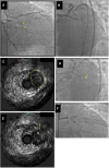
Example of identification of the proximal cap location by intravascular ultrasound (IVUS). (Panel A) Ostial chronic total occlusion (CTO) of the first obtuse marginal branch (arrow). (Panel B) The guidewire kept entering the distal circumflex during antegrade wire escalation approach. (Panel C,D) IVUS demonstrated that the CTO (yellow circle in Panel C) originated proximal (arrow in Panel D) to the distal circumflex's apparent origin. (Panel E) A Confianza Pro 12 guidewire was used for antegrade crossing and its location within the CTO was confirmed by IVUS. (Panel F) Confianza Pro 12 was advanced through the occlusion. Modified with permission from Brilakis ES. Manual of chronic total occlusion interventions a step-by-step approach. Second edition. ed. London: Elsevier/Academic Press; 2018.
Figure 4
Figure 4
Antegrade and retrograde guidewire positions as assessed by IVUS in reverse CART. (A) Antegrade and retrograde guidewires are both within intimal plaque. This is the ideal scenario to make a connection, after antegrade balloon dilation in the chronic total occlusion body. If needed, retrograde puncture of intimal plaque with a stiffer wire could be performed. (B) Antegrade and retrograde guidewires are both within the subintimal space. This is another ideal condition in which it is easy to create a connection in the same space after balloon dilation. (C) Antegrade guidewire in intimal plaque but retrograde guidewire in subintimal space. This is a very complex situation in which it is crucial to create a medial disruption with proper balloon sizing to create a connection between the two guidewires. In case of failure, it may be possible to advance the antegrade wire distally to enter the subintimal space and create the previous condition (subintimal–subintimal). (D) Antegrade wire in subintimal space but retrograde wire in intimal plaque, often very calcified. This is the most complex situation because antegrade balloon dilation usually enlarges the subintimal space (increasing intramural hematoma) with low probability of creating a connection between the two guidewires. In this situation, the connection is usually achieved by pushing the retrograde wire in the subintimal space (usually with retrograde knuckle technique). In such a complex case, a possible less-used alternative is retrograde balloon dilation (original CART) to create medial dissection and facilitate antegrade guidewire connection with the retrograde guidewire. CART, controlled antegrade retrograde tracking; IVUS, intravascular ultrasound. Modified with permission from Galassi AR, Sumitsuji S, Boukhris M, et al. Utility of intravascular ultrasound in percutaneous revascularization of chronic total occlusions: an overview. JACC Cardiovasc Interv 2016; 9:1979–91, Elsevier. Used with permission from Brilakis ES. Manual of chronic total occlusion interventions a step-by-step approach. Second edition. ed. London: Elsevier/Academic Press; 2018.
Figure 5
Figure 5
Proposed algorithm for IVUS use to facilitate reverse CART during CTO PCI. (A–D) corresponds to the various scenarios during reverse—CART. In (A) both antegrade and retrograde guide wires are positioned in the intraplaque space, in (B) both guide wires are in the subintimal space, in (C) the antegrade wire is intraplaque, whilst the retrograde wire is subintimal and finally in (D) the antegrade wire is subintimal, whilst the retrograde wire is intraplaque. During step 1, IVUS catheter is advanced over the antegrade wire in the overlapping segment between the antegrade and the retrograde wire. After the appropriate positioning of the IVUS catheter we aim to determine the true position of the two guide wires (intraplaque or subintimal). In step 2, according to each scenario we proceed with the most suitable strategy modification. For scenario A, we choose an 1 to 1 sized balloon to dilate the antegrade space and then with the support of a guide-extension catheter (Teleflex Trapliner is recommended as the integrated trapping balloon will facilitate exchange equipment) we aim to advance the retrograde wire inside the antegrade guide extension catheter. In scenario (B), where both guide wires are still in the same space but subintimally, we follow the same approach. In scenario (C), where the antegrade wire is intraplaque and the retrograde wire is subintimal we opt to dilate the antegrade space with larger balloons in order to create a connection-fenestration between the antegrade and the retrograde space and facilitate the retrograde wire, usually a stiff hydrophilic guide wire with good torqueability such as a Gaia 3rd (ASAHI INTECC), advancement into the antegrade space and guide catheter extension. In scenario (D), where the antegrade wire is subintimal and the retrograde wire is intraplaque, we aim to use extra-stiff retrograde guide wires such as Hornet 14, Confianza pro 12 in order to create a connection and facilitate retrograde wire tracking from the retrograde intraplaque position to the antegrade subintimal space and thus successful reentry into the antegrade space with retrograde wire advancement into the antegrade catheter. In the last two scenarios the additional use of the DRAFT technique (Deflate and Retract of the antegrade balloon followed by immediate advancement of the retrograde stiff guide wire) will further facilitate successful retrograde wire externalization.
Figure 6
Figure 6
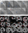
(A) Right coronary artery CTO (6Ai). In (6Ai, Aii) angiographic evidence of heavy calcification is noticed (blue arrows). Grenadoplasty is performed (6Aiii, blue arrow) to facilitate microcatheter and balloon crossing followed by rotational atherectomy. Undilatable lesion (6Av, blue arrow) was successfully treated with intravascular lithotripsy (6Avi, Avii, blue arrows). In (6Avi), the tension to the guide extension and catheter during balloon forward motion due to heavy vessel calcification is noticed (red arrow). Final angiographic result after successful CTO recanalization and plaque modification with combined grenadoplasty, rotational atherectomy and intravascular lithotripsy (6Aviii). (B) intravascular ultrasound pictures. Different modes of calcification including circumferential thick calcification (6Bi, 6Bv) and calcified nodules (6Bii–iv, red arrows). The effect of plaque modification techniques (grenadoplasty, rotational atherectomy and intravascular lithotripsy) is demonstrated in (6Bvi–x). Final intravascular images after successful stents insertion (6Bxi–xv).
Figure 7
Figure 7
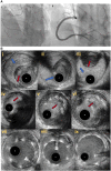
(A) Right coronary artery total occlusion revascularization with antegrade dissection reentry technique (7Ai–ii). (B) Intravascular ultrasound pictures after successful distal true lumen reentry and CTO recanalization. In (7Bi), intraluminal wire position (red arrow) with large subintimal haematoma is noticed. In (7Bii), the transition from true lumen into subintimal space is noticed (blue arrow), whilst in (7biii) the wire is in the subintimal space (blue arrow) that compresses the true lumen (red arrow). In (7Biv–vi), intraplaque wire tracking is noticed. Final IVUS images after stent deployement (7bvii–ix).
Figure 8
Figure 8
Follow up angiography in patient illustrated in figure 7, 3 months after successful RCA CTO PCI (8i). IVUS demonstrates significant stent vessel size mismatch and significant malapposition due to subintimal haematoma healing and vessel positive remodeling after successful PCI (8ii–iv). Angiographic (8v) and IVUS images (8vi–viii) after stent optimization to correct stent-vessel size mismatch and malapposition.
Figure 9
Figure 9
Proposed algorithm for intravascular imaging guided CTO PCI: precise evaluation of plaque characteristics and proper guidance for plaque modification, estimation of stent diameter and length and stent optimization post stent implantation. IVUS, Intravascular ultrasound; CTO, Chronic total occlusions; PCI, Percutaneous Coronary Intervention; EEL, external elastic lamina.
Figure 10
Figure 10
Intravascular imaging (IVUS) guided chronic total occlusion (CTO) percutaneous coronary intervention; (A) initial angiography with contralateral injections to define CTO lesion characteristics; (B) successful antegrade wire crossing; (C) final angiographic result after IVUS guided drug eluting stent (DES) implantation; (D) distal landing zone with reference cross sectional area and diameter estimated at 3 mm; (E) CTO segment cross-sectional area and reference diameter estimated at 4.5 mm; (F) proximal landing zone with reference cross sectional area and diameter estimated at 4.5 mm. The overall lesion length requiring stent coverage from distal landing zone was estimated at 65 mm and therefore two overlapping DES 3.0 × 38 mm and 4.0 × 38 mm were successfully implanted and post-dilated with 3.5 and 4.5 mm non-compliant balloons based on media to media reference diameters as per IVUS measurements; (G) distal stent cross-sectional area with excellent absolute (>5.5 mm2) and relative expansion (>100%); (H) proximal stent cross-sectional area with excellent relative expansion (>100%). Used with permission by Elsevier. Kalogeropoulos AS, Alsanjari, O, Davies, JR. et al. Impact of Intravascular Ultrasound on Chronic Total Occlusion Percutaneous Revascularization. Cardiovasc Revasc Med. 2021; 33:32–40.

Similar articles

Cited by

References

    1. Azzalini L, Carlino M, Bellini B, Marini C, Pazzanese V, Toscano E, et al. Long-term outcomes of chronic total occlusion recanalization versus percutaneous coronary intervention for complex non-occlusive coronary artery disease. Am J Cardiol. (2020) 125(2):182–8. 10.1016/j.amjcard.2019.10.034 - DOI - PubMed
    1. Gasparini GL, Oreglia JA, Milone F, Presbitero P. Avoid overtreatment in the setting of chronic total occlusions: the role of blood flow restoration in positive vascular remodeling. Int J Cardiol. (2015) 184:414–5. 10.1016/j.ijcard.2015.02.107 - DOI - PubMed
    1. Park JJ, Chae IH, Cho YS, Kim SW, Yang HM, Seo JB, et al. The recanalization of chronic total occlusion leads to lumen area increase in distal reference segments in selected patients: an intravascular ultrasound study. JACC Cardiovasc Interv. (2012) 5(8):827–36. 10.1016/j.jcin.2012.05.004 - DOI - PubMed
    1. Galassi AR, Tomasello SD, Crea F, Costanzo L, Campisano MB, Marzá F, et al. Transient impairment of vasomotion function after successful chronic total occlusion recanalization. J Am Coll Cardiol. (2012) 59(8):711–8. 10.1016/j.jacc.2011.10.894 - DOI - PubMed
    1. Zhang J, Gao X, Kan J, Ge Z, Han L, Lu S, et al. Intravascular ultrasound versus angiography-guided drug-eluting stent implantation: the ULTIMATE trial. J Am Coll Cardiol. (2018) 72(24):3126–37. 10.1016/j.jacc.2018.09.013 - DOI - PubMed