Review
. 2024 Jan;19(1):69-82.
doi: 10.1016/j.cpet.2023.08.002. Epub 2023 Sep 27.

High-resolution Imaging Using Virtual-Pinhole PET Concept

Affiliations
Review

High-resolution Imaging Using Virtual-Pinhole PET Concept

Yuan-Chuan Tai. PET Clin. 2024 Jan.

Abstract

Organ-specific PET scanners continues to draw interest for their high-resolution imaging capability that is unmatched by whole-body PET/computed tomography (CT) scanners. The virtual-pinhole PET concept offers new opportunities in PET system design, allowing one to mix and match detectors of different characteristics to achieve the highest performance such as high image resolution, high system sensitivity, and large imaging field-of-view. This novel approach delivers high-resolution PET images previously available only through organ-specific PET scanner while maintaining the imaging field-of-view of a clinical PET/CT scanner to see the entire body.

Keywords: Organ-specific PET imaging; PET; Positron emission tomography; Virtual-pinhole PET; Zoom-in PET imaging.


Conflict of interest statement

Disclosure The authors have nothing to disclose.

Figures

Figure 1.
Figure 1.
(A) A simplified pinhole SPECT system consists of a gamma camera and a pinhole collimator that can be rotated around a center-of-rotation. (B) A simplified virtual-pinhole PET system consists of a high-resolution detector array (#1) and a low-resolution detector array (#2) that can be rotated around a center-of-rotation. [Adapted from the Journal of Nuclear Medicine with Permission. doi:10.2967/jnumed.107.043034]
Figure 2.
Figure 2.
(A) An the experimental setup of a simplified virtual-pinhole PET system consists of a high-resolution detector array on the left and a low-resolution detector array on the right that can be rotated around an object at the center of the rotation stages. (B) A high-resolution PET detector array mounted to a rotation stage that is attached to the back side of a microPET scanner. (C) Front view of the insert device. The add-on detector is positioned closed to the central axis of the scanner to resemble the virtual-pinhole PET geometry. [Adapted from the Journal of Nuclear Medicine with Permission. DOI:10.2967/jnumed.107.043034 and DOI:10.2967/jnumed.107.044149]
Figure 3.
Figure 3.
A virtual-pinhole PET device with a full-ring of high-resolution PET detectors mounted to an existing animal PET scanner: (A) the device with its cover removed; (B) the device mounted to the back of a microPET F-220 scanner; (C) front view of scanner with the device attached. The animal port opening is reduced to 5.4 cm in diameter; (D) Schematic illustrating position of high-resolution detector ring relative to the detector rings in the native scanner. [Adapted from the Journal of Nuclear Medicine with Permission. J Nucl Med 2008; 49:1668–1676. DOI: 10.2967/jnumed.107.050070]
Figure 4.
Figure 4.
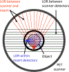
Three types of coincidence events (II, IS and SS) may be detected when a set of high-resolution detectors are inserted inside the imaging FOV of a PET scanner.
Figure 5.
Figure 5.
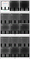
A micro-Derenzo phantom imaged by the virtual-pinhole PET device in Fig. 3. Images were reconstructed using SS, IS or II coincidence events separately, or jointly. Diameters of the fillable rods in the phantom are 0.8, 1.0, 1.25, 1.5, 2.0, and 2.5 mm, respectively. Profiles through 1-mm and 1.5-mm diameter rods are extracted from each image and shown below. The native scanner resolution (SS images) is improved when coincidence events measured by insert (II or IS) are included for image reconstruction. Jointly reconstructed images are less noisy than the high-resolution insert device alone (II image). [Adapted from the Journal of Nuclear Medicine with Permission. J Nucl Med 2008; 49:1668–1676. DOI: 10.2967/jnumed.107.050070]
Figure 6.
Figure 6.
(A) A dedicated PEM system with asymmetric geometry. Five point sources are located at (0,0), (−10,0), (0,6), (0, 10) and (0,−10) (in the unit of centimeter) relative to the origin at the scanner center. Coincidence events detected by lower-resolution detectors in the upper half-ring (SS events), between the two half-rings (IS events) and by the high-resolution detectors in the lower half ring (II events) are sorted to form the SS, IS and II sinograms in (B), (C), and (D), respectively. (E) combined sinogram of all events. [Adapted from IEEE Transactions on Nuclear Sciences with Permission. DOI: 10.1109/TNS.2006.869853]
Figure 7.
Figure 7.
A Total-breast PET imager constructed using 3 groups of detectors: anterior panel and “stadium”-shaped ring contain TOF and DOI capable high-resolution PET detectors while the posterior panel consists of TOF detectors similar to those used in clinical PET/CT systems. [Adapted from Physics in Medicine and Biology with Permission. DOI:10.1088/1361-6560/abfb16]
Figure 8.
Figure 8.
(A) Distribution of coincidence events detected by (ii) Biograph Vision PET Scanner and (iii) the total-breast PET imager for lesion diameter 4mm, 4:1 lesion-to-background ratio (L:B). Lesion placement map shown at left (i). (B) Iteratively reconstructed central-slice images of the torso phantom containing lesions of indicated sizes in each image, along with fixed L:B of 4:1 imaged by (top row) whole-body scanner and (bottom row) dedicated total-breast PET scanner. (C) Lesions with various indicated L:B along with a fixed lesion diameter of 4 mm imaged by (top row) whole-body scanner and (bottom row) dedicated total-breast PET scanner. [Adapted from Physics in Medicine and Biology with Permission. DOI:10.1088/1361-6560/abfb16]
Figure 9.
Figure 9.
A Siemens Biograph 40 PET/CT scanner with a prototype virtual-pinhole PET insert attached: (A) front view; (B) rear view. The virtual-pinhole PET insert gantry is supported by a 3D translation stage that positions the insert detectors concentrically with the scanner’s detector rings.
Figure 10.
Figure 10.
(A) The virtual-pinhole PET insert detector module contains a LSO array (13×13 elements) optically coupled to a multi-anode photomultiplier (MA-PMT) via a custom light guide. (B) 28 detector modules are arranged in a custom gantry to form 2 half-rings of 249 mm in diameter.
Figure 11.
Figure 11.
Ge-68 line sources imaged by the Biograph 40 PET/CT (top row) and the virtual-pinhole PET insert (bottom row). Profiles through 3 line sources show significant improvement in image resolution (> 40% reduction in FWHM) when the virtual-pinhole PET insert device is attached to the PET/CT scanner.
Figure 12
Figure 12
(Top) PET/CT images of a head-and-neck cancer patient scanned by a Biograph 40 scanner. (Bottom) The same patient imaged by the prototype virtual-pinhole PET insert device.
Figure 13.
Figure 13.
(a) Geometry of the Monte Carlo simulation study using the prototype virtual-pinhole PET insert for breast imaging. (b) Magnified view of the breast region showing 6 groups of spherical tumors (2, 3, 4, 6, 8, and 12 mm in diameter, respectively). Tumor-to-Background ratio (T/B) was 3, 6, 9, or 12. Simulated acquisition time was 2.26 or 6.78 minutes. [Adapted from Physics in Medicine and Biology with Permission. doi:10.1088/0031-9155/58/18/6407]
Figure 14.
Figure 14.
(Top) Images from the native PET scanner. (Bottom) Images from the virtual-pinhole PET insert system. [Adapted from Physics in Medicine and Biology with Permission. doi:10.1088/0031-9155/58/18/6407]
Figure 15.
Figure 15.
(a) A torso phantom with a breast compartment was imaged using the virtual-pinhole PET insert prototype in a Biograph 40 PET/CT scanner. (b) The breast compartment contains 6 clusters of spherical lesions with their size ranging from 3.3 to 11.4 mm in diameter. The virtual-pinhole PET images (right) exhibit higher resolution in the breast and axilla region than the native scanner images (left) [Adapted from Physics in Medicine and Biology with Permission. doi:10.1088/0031-9155/58/18/6407]
Figure 16.
Figure 16.
(a) The second generation virtual-pinhole PET insert system comprises of compact high-resolution PET detectors in a flat-panel enclosure that can be positioned anywhere around a patient’s body by a robotic arm. (b) Six clusters of spherical lesions are embedded in a torso phantom and filled with radioactivity with blue dye. The activity concentration has a 6:1 T/B ratio. [Adapted from Medical Physics with Permission. doi:10.1002/mp.13724]
Figure 17.
Figure 17.
(a) From left to right are native scanner image, and images reconstructed using combined datasets when the insert device was placed below and to the left of the phantom to mimic a dual-panel virtual-pinhole PET insert device, and a dual-panel DOI-capable virtual-pinhole PET insert device that can triple the number of IS events; (b) the CRC curves for different configurations (Left) and the CRC ratios with and without the virtual-pinhole PET insert (Right). [Adapted from Medical Physics with Permission. doi:10.1002/mp.13724]

Similar articles

Cited by

References

    1. Gallagher BM, Ansari A, Atkins H, et al. Radiopharmaceuticals XXVII. 18F-labeled 2-deoxy-2-fluoro-d-glucose as a radiopharmaceutical for measuring regional myocardial glucose metabolism in vivo: tissue distribution and imaging studies in animals. J. Nucl. Med 1977;18(10):990–6 - PubMed
    1. Kuhl DE, Phelps ME, Hoffman EJ, Robinson GD Jr., MacDonald NS. Initial clinical experience with 18F-2-fluoro-2-deoxy-d-glucose for determination of local cerebral glucose utilization by emission computed tomography. Acta Neurol. Scand. Suppl 1977;64:192–3 - PubMed
    1. Gallagher BM, Fowler JS, Gutterson NI, MacGregor RR, Wan CN, Wolf AP. Metabolic trapping as a principle of oradiopharmaceutical design: some factors resposible for the biodistribution of [18F] 2-deoxy-2-fluoro-D-glucose. J. Nucl. Med 1978;19(10):1154–61 - PubMed
    1. Som P, Atkins HL, Bandoypadhyay D, et al. A fluorinated glucose analog, 2-fluoro-2-deoxy-D-glucose (F-18): nontoxic tracer for rapid tumor detection. J. Nucl. Med 1980;21(7):670–5 - PubMed
    1. Warburg O, Wind F, Negelein E. The metabolism of tumors in the body. J Gen Physiol 1927;8:519–30 - PMC - PubMed

MeSH terms

LinkOut - more resources