A hull reconstruction-reprojection method for pose estimation of free-flying fruit flies
- PMID: 37795876
- PMCID: PMC10629692
- DOI: 10.1242/jeb.245853
A hull reconstruction-reprojection method for pose estimation of free-flying fruit flies
Abstract
Understanding the mechanisms of insect flight requires high-quality data of free-flight kinematics, e.g. for comparative studies or genetic screens. Although recent improvements in high-speed videography allow us to acquire large amounts of free-flight data, a significant bottleneck is automatically extracting accurate body and wing kinematics. Here, we present an experimental system and a hull reconstruction-reprojection algorithm for measuring the flight kinematics of fruit flies. The experimental system can automatically record hundreds of flight events per day. Our algorithm resolves a significant portion of the occlusions in this system by a reconstruction-reprojection scheme that integrates information from all cameras. Wing and body kinematics, including wing deformation, are then extracted from the hulls of the wing boundaries and body. This model-free method is fully automatic, accurate and open source, and can be readily adjusted for different camera configurations or insect species.
Keywords: Drosophila; Biolocomotion; Insect flight; Kinematics; Motion capture; Tracking.
© 2023. Published by The Company of Biologists Ltd.
Conflict of interest statement
Competing interests The authors declare no competing or financial interests.
Figures


 is obtained by reconstructing the body images in all four views. Expanded wing hulls
  are obtained by reconstructing a wing-only image in one view (here, j=1) and the entire fly image in the remaining three views. Expanded body hulls,
  are obtained similarly. (B) The body hull (dark green) with head and tail blobs (light green). Wing hulls are divided into top and bottom halves (blue/cyan, red/magenta), with the stripes to first approximate wing center of mass (CM; black/gray). (C) Reprojection of
  onto the image plains allows us to identify otherwise-occluded pixels. Here, the raw image is superposed with the span vector (black), the identified reprojected wing pixels and their boundaries, divided into leading edge (LE) and trailing edge (TE), as well as the body pixels reprojected from
  . (D) Body hull with the wing-boundary hulls divided into LE (blue/red) and TE (cyan/magenta) voxels. Also shown are the body axes xb, and the stroke plane (pink) with its normal (magenta). (E) Quantifying wing deformation by calculating five local chord vectors along the wing span, based on the wing boundary voxels (red/blue).
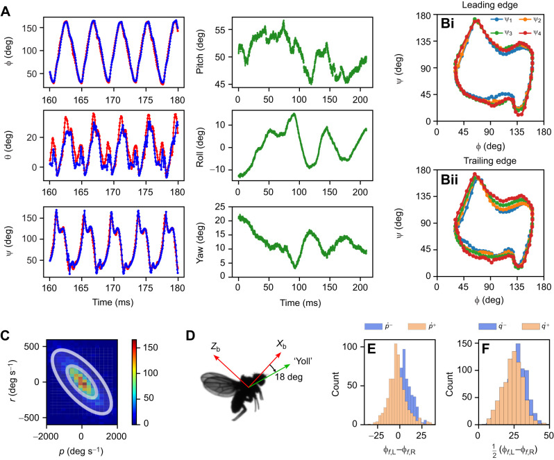
 . For
. For  >3×10⁵ deg s–2 (orange), the left wing reaches more forward than the right wing and vice versa, indicating that moderate roll acceleration is obtained by front φ asymmetry. (F) Histograms of the mean front stoke angle per wingbeat, split
  . For
. For  >3×10⁵ deg s–2 (orange), the front φ distribution is skewed to the left, indicating that pitch acceleration is achieved by symmetric control of the front stroke angle.
References
Publication types
MeSH terms
Grants and funding
LinkOut - more resources
Full Text Sources
Molecular Biology Databases