. 2023 Oct 13;14(1):6445.
doi: 10.1038/s41467-023-41977-1.

Tunable encapsulation of sessile droplets with solid and liquid shells

Affiliations

Tunable encapsulation of sessile droplets with solid and liquid shells

Rutvik Lathia et al. Nat Commun. .

Erratum in

Abstract

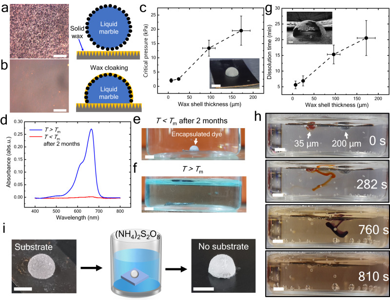
Droplet encapsulations using liquid or solid shells are of significant interest in microreactors, drug delivery, crystallization, and cell growth applications. Despite progress in droplet-related technologies, tuning micron-scale shell thickness over a large range of droplet sizes is still a major challenge. In this work, we report capillary force assisted cloaking using hydrophobic colloidal particles and liquid-infused surfaces. The technique produces uniform solid and liquid shell encapsulations over a broad range (5-200 μm shell thickness for droplet volume spanning over four orders of magnitude). Tunable liquid encapsulation is shown to reduce the evaporation rate of droplets by up to 200 times with a wide tunability in lifetime (1.5 h to 12 days). Further, we propose using the technique for single crystals and cell/spheroid culture platforms. Stimuli-responsive solid shells show hermetic encapsulation with tunable strength and dissolution time. Moreover, scalability, and versatility of the technique is demonstrated for on-chip applications.


Conflict of interest statement

The patent related to this paper has been awarded by the Indian patent office (Application no. 202241047688, Patent no. 445807, Submitted by Indian Institute of Science, Bangalore). R.L., S.N., C.D.M. and P.S. are the inventors of the patent. The remaining authors declare no competing interests.

Figures

Fig. 1
Fig. 1. The tunable liquid and solid shells using the LMOI method.
a Liquid Marble on silicone oil (50 cP viscosity) infused surface in which oil rises to cover the LM as time progresses. The volume of the inner liquid is 10 µL, and the particle size is 35 µm PTFE. Entire LM cloaking can be seen in the initial 2 to 4 min. Scale bar = 1 mm. b Schematic representation of LMOI (Liquid marble on an oil-infused surface) where the coating of particle and oil is represented on an OI (liquid/oil-infused) surface. c A confocal microscope image shows the thickness of the silicone oil coating for LM and droplet (inset). Scale bars = 200 µm. d Stability of LMOI for different oils. A negative value of Γ=γowγo represents an unstable coating where crack formation in LMOI is present (inset: LMOI – neem oil). A positive value of Γ=γowγo represents a stable coating where no crack formation in LMOI is observed (Inset: LMOI – mineral oil). Scale bar = 1 mm. Measurements were carried out on n = 3 independent samples, and data are presented as mean values ± SD. Black dots represent individual data points. e LMOI prepared from 200 µL liquid volume. Scale bar = 2 mm. Inset: LMOI prepared from 14 nL liquid volume. Scale bar = 300 µm. f SEM image of a half-cut dried capsule based on PTFE particles. Scale bar = 400 μm. g SEM image of a half-cut dried capsule based on hydrophobic glass particles (35 μm). Scale bar = 400 μm. The red-dotted region represents the shell wall where spherical glass beds are visible through the cloaked layer of wax. Scale bar = 20 μm. h Shell thickness is represented as a function of particle size. Inset: SEM image of the PTFE shell wall. Scale bar = 40 µm. Measurements were carried out on n = 3 independent samples, and data are presented as mean values ± SD. i, The uniformity of the shell wall for different PTFE particle sizes. Measurements were carried out at 3 different regions, namely, the bottom left (orange color), top (blue color), and bottom right (purple color) parts of the capsule on n = 3 independent samples, and data are presented as mean values ± SD. Black dots represent individual data points. A detailed depiction of the locations is given in Supplementary Fig. 4. Source data are provided as a Source Data file.
Fig. 2
Fig. 2. The dynamics of oil-cloaking.
a The snapshots of oil rise in 10 μL LM with 35 μm PTFE particles and 50 cP silicone oil. Scale bar = 1 mm. b The evolution of normalized rising height (y/h) with time for different silicone oil viscosity (10 cP – black color, 20 cP – red color, 50 cP – blue color, and 100 cP – green color). Measurements were carried out on n = 3 independent samples, and data are presented as mean values ± SD. c The scaled graph collapses into a single curve with a slope of 0.5 (black line) for all viscosity. Measurements were carried out on n = 3 independent samples, and data are presented as mean values ± SD. Source data are provided as a Source Data file.
Fig. 3
Fig. 3. Control of evaporation rate.
a Comparison of the temporal evolution of the normalized mass (m/m0) of the droplet and LM in different configurations. Such configurations are droplet on SHP (red) and OI surface (silicone – green and mineral – cyan), LM on SHP surface (black), and LMOI based on silicone (blue) and mineral oil (magenta). The volume of the LM and droplet is 10 µL. All experiments were repeated n = 3 times independently, and the mean is plotted. b Schematic of LMOI defining various parameters important in the evaporation process where red color represents the oil layer and blue color region represents the water. c Comparison of the temporal evolution of normalized mass with the theoretical model. d High-temperature stabilization of 10 µL LMOI with mineral (blue color) and silicone (red color) oil. Measurements were carried out on n = 3 independent samples, and data are presented as mean values ± SD. e Effect of silicone oil viscosity on evaporation time of the 10 µL LMOI. The green dotted line divides the full and partial cloaking of LM (inset for schematic) based on viscosity. Measurements were carried out on n = 3 independent samples, and data are presented as mean values ± SD. f Tunability of evaporation rate by changing the oil and particle coating density/mass loading. In the horizontal axis, Si and Mi prefixes indicate the LMOI with silicone oil (purple color) and mineral oil (blue color); the suffix number represents the mass loading of the particle on LMOI in µg mm−2. Insets represent the confocal images of the different mass loaded LMOI. Scale bars = 200 µm. Measurements were carried out on n = 3 independent samples, and data are presented as mean values ± SD. Black dots represent individual data points. All experiments are performed at 25 ± 2 °C and (50 ± 3)% relative humidity. Source data are provided as a Source Data file.
Fig. 4
Fig. 4. Crystal growth in tunable LMOI liquid shell.
Photograph of the crystals made from LMOI. Scale bar = 1 mm. a Pentahydrate copper sulfate b Rochelle salt c, sodium nitrate, and d, lysozyme protein. For lysozyme, the Scale bar = 100 μm. e Variable size crystals of copper sulfate were prepared by changing the volume of LMOI from 5 to 60 µL. Scale bar = 1 mm. The XRD plot confirms a single crystal of  f, pentahydrate copper sulfate, g Rochelle salt, and h, sodium nitrate crystals produced from LMOI. Insets represent XRD of the crystals produced from the droplet evaporation on OI, where the polycrystalline structure is evident. i Polarization-electric field (PE) hysteresis loop at 20 °C for the single crystal Rochelle salt crystal produced from LMOI. The data confirms ferroelectric behavior of the Rochelle salt crystal. Inset: a Rochelle salt crystal attached to a printed circuit board (PCB) for PE measurement. Scale bar = 2 mm. j Schematic and k, photograph of the automated setup for the large number fabrication of LMOI. Where the droplet is formed via a syringe and then rolled onto a slant powder/particle bed. Due to the rolling of the droplet, the hydrophobic particle settles at the interface of the droplet and forms an LM. Then, the prepared LM falls gently on the oil-infused surface. The surface is mounted on the automated X-Y stage. Scale bar = 8 mm. Source data are provided as a Source Data file.
Fig. 5
Fig. 5. LMOI as a biological reactor.
Hanging LMOI configuration as a, schematic and b, photograph. Scale bar = 1 mm. c, The cluster of ovarian cancer cells after 18 h of LMOI incubation at 37 °C and 5% CO2. Scale bar = 50 µm. d Comparison of ovarian cancer cell viability in hanging LMOI (blue) and hanging droplet (red). Measurements were carried out on n = 3 independent samples, and data are presented as mean values ± SD. e Fluorescence photomicrographs were acquired at different time points for ovarian cancer cells, where cyan color represents live cells (due to staining with calcein acetoxymethyl ester), and magenta color represents the dead cells (due to staining with propidium iodide). Scale bar = 50 µm. f Yeast cell growth inside an LMOI at different time points. Scale bar = 50 µm. g Normalized yeast cell count variation with time where the number of yeast cells at a particular instance was normalized by the initial number of cells (at 0 h). The exponential growth can be seen for up to 20 h (green dotted line). However, after that, stabilization in growth is observed. Measurements were carried out on n = 3 independent samples, and data are presented as mean values ± SD. Inset: glucose levels of the yeast solution tested by Benedict’s solution. Red, yellow, and green colors indicate glucose levels of more than 2%, 1%, and 0.5%, respectively. Scale bar = 1 mm. Source data are provided as a Source Data file.
Fig. 6
Fig. 6. Solid shell temperature-responsive encapsulation.
A wax-infused nanostructured surface and stabilization of LM at a, T < Tm and b, T > Tm, Scale bar = 200 μm. c Required critical pressure to break the capsule. Inset: photograph of a capsule. Measurements were carried out on n = 3 independent samples, and data are presented as mean values ± SD. Scale bar= 2 mm. d, The absorbance spectra of the water in which the MB capsule was placed for e, 2 months at T < Tm (blue color) and f, T > Tm (red color). The absence of an absorbance signal at 664 nm suggests no diffusion of MB into water even after 2 months of immersion. Scale bar = 2 mm. g The time to dissolve the wax shell if the temperature of the fluid bath increases above melting temp (T ≈ 90 °C). Measurements were carried out on n = 3 independent samples, and data are presented as mean values ± SD. Inset: ruptured capsule under SEM. Scale bar = 200 μm. h, The tunability of release: two capsules with different shell thickness and filled with dye were placed in water at T ≈ 90 °C. Encapsulated dye placed in water where lower thickness (≈ 35 μm, red color) capsule ruptures early, releasing the inner liquid. In comparison, a higher thickness (≈ 200 μm, purple color) capsule ruptures after a prolonged duration. Scale bar = 2 mm. i, Removal of the capsule from the substrate by etching the surface in ammonium persulfate solution. Scale bar = 2 mm. Source data are provided as a Source Data file.
Fig. 7
Fig. 7. Functionalities of the LMOI platform.
a LM on a structured surface where the bottom pattern is invisible. b Transparency of LMOI (silicone oil) where a clear pattern is visible through LMOI. Scale bar = 2 mm. c Comparison of transparency between water droplet, LMOI (silicone oil), and LM for two different laser wavelengths, i.e., 633 nm (dark orange) and 532 nm (dark cyan). Measurements were carried out on n = 3 independent samples, and data are presented as mean values ± SD. Black dots represent individual data points. d Critical normalized deformation (ΔL/L) before merging for different configurations. L represents the bare liquid droplet, and OL represents the liquid droplet covered with an oil layer. LMOI (silicone oil) has been used throughout the experiments. Inset: merging photographs for different configurations. Measurements were carried out on n = 3 independent samples, and data are presented as mean values ± SD. Black dots represent individual data points. Scale bar = 2 mm. e Ferrofluid-based LMOI, where uncoating of the particle layer can be performed with the help of a magnet. Scale bar = 2 mm. f, Merging occurs when a magnet is brought closer to the non-merging LMOI – ferrofluid. Scale bar = 2 mm. Source data are provided as a Source Data file.

References

    1. Lathia R, et al. Advances in Microscale Droplet Generation and Manipulation. Langmuir. 2023;39:2461–2482. doi: 10.1021/acs.langmuir.2c02905. - DOI - PubMed
    1. Garstecki P, Kaminski STS, Garstecki P, Kaminski TS. Controlled droplet microfluidic systems for multistep chemical and biological assays. Chem. Soc. Rev. 2017;46:6210–6226. doi: 10.1039/C5CS00717H. - DOI - PubMed
    1. Baccouche A, et al. Massively parallel and multiparameter titration of biochemical assays with droplet microfluidics. Nat. Protoc. 2017;12:1912–1932. doi: 10.1038/nprot.2017.092. - DOI - PubMed
    1. Bansal S, Sen P. Electrowetting based local sensing of liquid properties using relaxation dynamics of stretched liquid interface. J. Colloid Interface Sci. 2020;568:8–15. doi: 10.1016/j.jcis.2020.02.035. - DOI - PubMed
    1. Nightingale AM, et al. Monitoring biomolecule concentrations in tissue using a wearable droplet microfluidic-based sensor. Nat. Commun. 2019;10:1–12. doi: 10.1038/s41467-019-10401-y. - DOI - PMC - PubMed