Review
. 2023 Sep 26;16(19):6405.
doi: 10.3390/ma16196405.

From Triboelectric Nanogenerator to Hybrid Energy Harvesters: A Review on the Integration Strategy toward High Efficiency and Multifunctionality

Affiliations
Review

From Triboelectric Nanogenerator to Hybrid Energy Harvesters: A Review on the Integration Strategy toward High Efficiency and Multifunctionality

Yifei Wang et al. Materials (Basel). .

Abstract

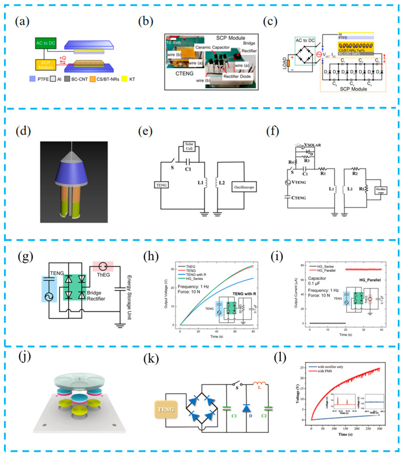
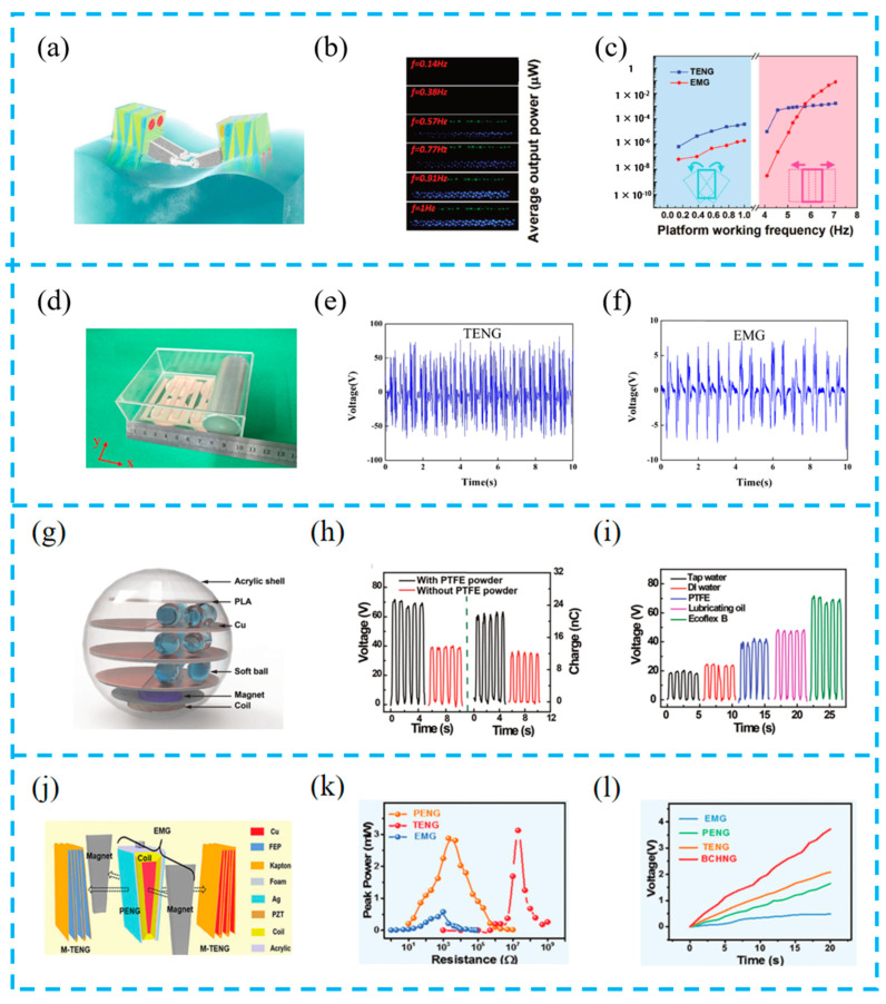
The rapid development of smart devices and electronic products puts forward higher requirements for power supply components. As a promising solution, hybrid energy harvesters that are based on a triboelectric nanogenerator (HEHTNG) show advantages of both high energy harvesting efficiency and multifunctionality. Aiming to systematically elaborate the latest research progress of a HEHTNG, this review starts by introducing its working principle with a focus on the combination of triboelectric nanogenerators with various other energy harvesters, such as piezoelectric nanogenerators, thermoelectric/pyroelectric nanogenerators, solar cells, and electromagnetic nanogenerators. While the performance improvement and integration strategies of HEHTNG toward environmental energy harvesting are emphasized, the latest applications of HEHTNGs as multifunctional sensors in human health detection are also illustrated. Finally, we discuss the main challenges and prospects of HEHTNGs, hoping that this work can provide a clear direction for the future development of intelligent energy harvesting systems for the Internet of Things.

Keywords: hybrid energy harvesters; multifunction; performance improvement; triboelectric nanogenerators.


Conflict of interest statement

The authors declare no conflict of interest.

Figures

Figure 1
Figure 1
Recent progress of HEHTNGs.
Figure 2
Figure 2
Four fundamental modes of TENGs: (a) vertical contact-separation mode, (b) lateral sliding mode, (c) single-electrode mode, (d) freestanding triboelectric layer mode.
Figure 3
Figure 3
Schematic diagram of device working principle: (a) PENG, (b) PyENG, (c) TEG, (d) SC, (e) EMG.
Figure 4
Figure 4
(a) TCO-HG composed of rotational triboelectric nanogenerator (TENG) and piezoelectric nanogenerator (PENG)/TENG hybrid generator; (b) open-circuit voltage and (c) closed-circuit current output of the TCO-HG with the rectifier circuit; reprinted from [80] with permission from research. (d) Schematic diagram of the TPENG structure; the voltage (e) and transferred charge (f) for the TPENG with point contact and without point contact under certain pressure by COMSOL software package (https://cn.comsol.com/); reprinted from [81] with permission from Elsevier. (g) The schematic illustration of S-TEHG; (h) rectified voltage and (i) current output; reprinted from [82] with permission from Elsevier. (j) Schematic illustration of the local view of the HEHD, which mainly consists of TENGs and EMGs as well as the commercial SCs; (k) the corresponding relationship between the VOC, ISC, and wind speed of the TENG 1; (l) dependence of the VOC and ISC of the EMG 1 on the wind speed; reprinted from [83] with permission from Elsevier.
Figure 5
Figure 5
(a) Different views of 3D virtualization by SRXTM analysis of CS/BT-NRs 7 wt.% composite film, with an inset of the TEM image for BT-NRs; (b) average maximum voltage output and average maximum current output (c) with a tendency for varying amounts of BT-NRs fillers (0, 3, 7, 10, 12, and 15 wt.%) and composited films; reprinted from [86] with permission from Elsevier. (d) Schematic illustration of the fabrication process of an LPPS-NFC-based TPENG device; (e) the output voltage and current (f) of LPPS-NFC-based TPENG under 0%, 25%, and 50% strain; reprinted from [87] with permission from Wiley Online Library. (g) Schematic illustration of the Fab-EH and a role of each component for TrG (left) or ThG (right) operation; measured (h) VOC and ISC (i) under bending motion; reprinted from [88] with permission from Elsevier. (j) Three-dimensional view of the HNG. Rectified separated (k) output voltage and (l) output current of each energy harvesting device in the HNG; reprinted from [89] with permission from Elsevier.
Figure 6
Figure 6
(a) Structure diagram of the PTNG and surface and cross-section SEM images of the aerogel bulk; (b) the optimal output voltage and (c) current of the quenched PANI/PVDF-TrFE PTNG; reprinted from [91] with permission from Elsevier. (d) The schematic diagram of PT-NG; (e) XRD pattern of PVDF films before and after modification with TiO2 nanoparticles; (f) FTIR absorption of PVDF films before and after modification with TiO2 nanoparticles; reprinted from [92] with permission from Elsevier. (g) Schematic of the composite silicone rubber; (h,i) output performance of composite silicone rubber under different conditions; reprinted from [93] with permission from Elsevier. (j) Cashew nut as a source for the production of cardanol oil and chemical structure of cardanol with the indication of the polar group and lipophilic chains; (k,l) open-circuit voltage and short-circuit current generated by the hybrid PENG under finger tapping (∼2 N, ∼5 Hz) and with a 10 MΩ probe; reprinted from [94] with permission from ACS.
Figure 7
Figure 7
(a) Schematic diagram of the smart solar panel umbrella system at closed state under sunny mode and open state under rainy mode; practical Voc (b) and Isc (c) outputs of the IDE-TENG using a shower connected with a household faucet for simulation of the rain scenario; reprinted from [95] with permission from Elsevier. (d) Schematic diagram of the R-TENG array; (e) current density (J–V) and power density (P–V) curves of the commercial solar cell unit with/without the R-TENG at ambient light intensity of 500 Lux, which is approximate to the outdoor light intensity in overcast and rainy weather; (f) power of the solar cell unit with/without R-TENG and the power loss of the solar cell unit under the influence of R-TENG at different ambient light intensities; reprinted from [96] with permission from Wiley Online Library. (g) Structural design and detailed components of the proposed whirligig-HNG; electrical output performance of the TENG at different frequencies of pulling force, which include VOC (h), ISC (i); reprinted from [97] with permission from Springer. (j) The structure of the hybrid generator; (k) output voltage and (l) current of the TENG part; reprinted from [98] with permission from Elsevier.
Figure 8
Figure 8
(a) Schematic diagram of the Al/CsPbBr3 system under sunlight; (b) VOC and (c) ISC output of the TENG based on a dynamic Al/CsPbBr3 Schottky junction under AM 1.5 G sunlight or in a dark environment at a speed of 0.7 ms−1; reprinted from [99] with permission from Wiley Online Library. (d) A schematic diagram; open-circuit voltage (e) and short-circuit current (f) of PVDF-based TENG; reprinted from [100] with permission from Elsevier. (g) Schematic diagram of the MCHCFS illustrating applied force distribution across different HNGs; (h) output voltage from the HNGs within the MCHCFS when a force is applied only on top T1 HNG; (i) schematic diagram of the electrical circuit implemented in MCHCFS; reprinted from [101] with permission from Wiley Online Library. (j) Film schematic diagram; (k) the PTEG thermoelectric open-circuit output voltage and output power increased with the temperature difference and reached 82.4 V and 7.54 μW, respectively, at a temperature difference of 50 °C; (l) the dependence of the PTEG thermoelectric output power on various load resistances at different temperature differences indicated that the maximum load output power was 1.32 μW when the temperature difference and load resistance were 50 °C and 0.9 kΩ, respectively; reprinted from [102] with permission from ACS.
Figure 9
Figure 9
(a) Schematic diagram of the internally charged CTENG excitation; (b) real CTENG device and electronic components; (c) circuit diagram of the internally charged excitation system; reprinted from [86] with permission from Elsevier. (d) Structure design; (e) schematic diagram of the self-driving wireless transmission system and (f) the equivalent circuit of the system; reprinted from [103] with permission from Royal Society of Chemistry. (g) Circuit diagrams for charging capacitor; (h) capacitor charging curves comparing the output voltage by changing the input conditions of only ThEG, only TENG, TENG with resistor, and hybrid device with series connection; (i) output current from the capacitor using hybrid devices with series connection and parallel connection; reprinted from [104] with permission from Wiley Online Library. (j) Schematic diagram of the EMG; (k) the circuit diagram of the power management system (PMS) for TENG; (l) charging curve with a single rectifier and PMS to charge 4700 µF capacitor; reprinted from [105] with permission from Wiley Online Library.
Figure 10
Figure 10
(a) Working sketch of the hybrid nanogenerator as a self-powered ocean environment monitoring tool; (b) temperature signal, humidity signal, GPS signal, and sound signal tracking using a computer LabVIEW (https://www.21ic.com/ni/labview.html); (c) circuit diagram of the self-powered wireless monitoring system; reprinted from [106] with permission from Science press. (d) Architecture of a self-powered human motion monitoring system for IoT applications; (e) conceptual illustration for monitoring various human motions; (f) photograph for demonstrating self-powered wireless human motion; reprinted from [107] with permission from Wiley Online Library. (g) Photograph of 240 LEDs lighted directly by the TENG in the MIWEH; (h) schematic circuit diagram of the self-powered marine environment monitoring system; (i) photograph of self-powered illuminance/temperature/pH value of marine environment monitoring and wireless signal transmission system; reprinted from [108] with permission from Elsevier. (j) Charging of a Li-ion battery of 30 mA h; (k) charging characteristic curve of the hybrid generator during the charging of a 30 mA h Li-ion battery; (l) photograph of the self-powered temperature and vibration wireless monitoring system; reprinted from [109] with permission from Science Press.
Figure 11
Figure 11
(a) Design of a synergetic hybrid piezoelectric–triboelectric wind energy harvester (SHPTWEH); (b) comparison of piezoelectric wind energy harvesters with and without boundaries; (c) the capacitor charging characteristics of the SHPTWEH with a 14 m/s wind; reprinted from [110] with permission from Elsevier. (d) Photograph of ES-ETHG device; (e) conceptual diagram of SDWS; (f) voltage, current, and the peak power density of EMG change with different load resistance (300 rpm); reprinted from [111] with permission from ACS. (g) Application scenario of the FTEHG on a ship and in a port; (h) working range of wind speed of the three generators, which indicates that the FS-TENG has the minimum response wind speed; (i) demonstration of FTEHG for powering electronic devices; reprinted from [112] with permission from ACS. (j) Expanded structural schematic of TEHG. Electrical measurements of the TEHG; (k) open-circuit voltage Voc; (l) short-circuit current Isc; reprinted from [113] with permission from Wiley Online Library.
Figure 12
Figure 12
(a) Schematic illustration of the arrayed device to simulate actual rainfall; (b) arrangement diagram of the common electrode R-TENG array; (c) charging voltage on different capacitors charged by the R-TENG array; reprinted from [96] with permission from Wiley Online Library. (d) Three-dimensional representation of the custom-made setup for simulating rainfalls; (e) the open-circuit voltage of the HNG under impact of single 100 µL water droplets; (f) the open-circuit voltage of the HNG under the impact of single raindrops at different frequencies in the range of 2–12 Hz; reprinted from [114] with permission from Elsevier. (g) Image of the PTHG fixed to the holder and driven by simulated water dropping; (h) the corresponding voltage output of the simulated water dropping in the on and off state; (i) the output voltage of PTHG linearly increases from 3.8 ± 0.43 to 20.1 ± 2.1 V with the input of simulated water rate dropping from 1 to 10 mL/s; reprinted from [115] with permission from Express Polymer Letters. (j) Device structure diagram; the output voltage (k) and current output (l) are at different tilt angles; reprinted from [95] with permission from Elsevier.
Figure 13
Figure 13
(a) Structure scheme of the HR-TENG; (b) the open-circuit voltage of the HR-TENGs under the same acoustic wave condition; (c) the open-circuit voltage of the HR-TENGs at different acoustic frequencies; reprinted from [116] with permission from Wiley Online Library. (d) The front optical images of the hybridized TENGs; (e) Voc and (f) Isc of the S-TENG with different sound pressures; reprinted from [117] with permission from Elsevier. (g) Schematic diagram of the realization from sound to electricity with the fabricated PHVAH; (h) output voltages and currents of PHVAH with different external loading resistance; (i) areal power densities of PHVAH with different external loading resistances; reprinted from [118] with permission from ACS. (j) Structure diagram of the MCPP ANG and SEM images of the aerogel bulk; (k) output voltage and current of the MCPP ANG with different external loads; (l) output power density of the MCPP ANG with different external loads; reprinted from [119] with permission from Elsevier.
Figure 14
Figure 14
(a) Structural design of ocean energy hybrid nanogenerator; (b) photographs of LED arrays supplied by TENG and EMG under shaking mode; (c) the average output powers for both TENG and EMG under varied platform working frequencies with LED loads; reprinted from [120] with permission from Wiley Online Library. (d) Picture of the triboelectric–electromagnetic hybrid nanogenerator. The electrical output performance of TENG and EMG; (e) the open-circuit voltage of TENG; (f) the open-circuit voltage of EMG; reprinted from [121] with permission from Elsevier. (g) Schematic illustration of the concept design for TEHG; (h) open-circuit voltage and transferred charge of the SB-TENG using two softballs with and without PTFE powder; (i) variation in the induced voltage with the types of the filled liquid; reprinted from [122] with permission from Wiley Online Library. (j) Structural components for BCHNG with three kinds of generators; (k) the corresponding peak-power–resistance profiles of the BCHNG module with three kinds of generators; (l) the charge curve of three kinds of generators and BCHNG modules; reprinted from [123] with permission from Wiley Online Library.
Figure 15
Figure 15
(a) Schematic of PEDOT:PSS coated triboelectric S2-sock integrated with PZT force sensors for diversified applications; comparisons of open-circuit voltage (b) and short-circuit current (c) between PEDOT:PSS-coated sock and original sock; reprinted from [125] with permission from ACS. (d) The schematic diagram of the basic structure of wearable non-contact free-rotating hybrid nanogenerator (WRG); the continuous output voltage/current of EMG (e) and TENG (f) at a 1 Hz frequency load press; reprinted from [126] with permission from Wiley Online Library. (g) Schematic and an optical image of the encapsulated hybrid PZ device; energy generation from the EG-skin attached on (h) forearm by tapping the hand to stimulate the muscle; (i) elbow by bending and releasing; reprinted from [127] with permission from Elsevier. (j) Exploded view of the HS with indication of the stacking sequence of layers and of the piezoelectric and triboelectric components; (k) 3D representation of the WHS embedded in the PDMS-Neoprene shoe sole; (l) application of the WHS for sensing human hand gestures (i) and photo (ii) of a human hand with five WHS sensors attached at its back. (iii) Voltage signal for the full extension of the index finger; reprinted from [128] with permission from Wiley Online Library.
Figure 16
Figure 16
(a) Schematic for large-scale and continuous fabrication of TPNG; (b) (i) images of a TPNG located in the subdermal chest region at two different scales; (ii) schematic of the energy harvesting process and circuit applied to collect energy from a beating rat heart; (c) current signals of implanted TPNG are associated with the beating heart; reprinted from [131] with permission from Wiley Online Library. (d) Schematic illustration to show the concept and working principle of artificial EG-skin using silk hydrogel; (e) chest for monitoring respiration cycles and (f) embedded in chicken breast tissue; reprinted from [127] with permission from Elsevier. (g) Structure diagram of FI-NES system; (h) small animal X-rays; (i) the time curve of the output PSR-ES driven by respiratory motion when SD rats are under different physiological states; reprinted from [132] with permission from Wiley Online Library. (j) Conception graph of an implanted HEHS harvesting biomechanical energy and biochemical energy in body; (k) structure diagram; (l) output voltage of rectified TENG, GFC, and their hybrid device; reprinted from [127] with permission from Springer.

References

    1. Xu C., Yang Y., Gao W. Skin-interfaced sensors in digital medicine: From materials to applications. Matter. 2020;2:1414–1445. doi: 10.1016/j.matt.2020.03.020. - DOI - PMC - PubMed
    1. Chandrarathna S.C., Graham S.A., Ali M., Ranaweera A.L.A.K., Karunarathne M.L., Yu J.S., Lee J.W. Analysis and Experiment of Self-Powered, Pulse-Based Energy Harvester Using 400 V FEP-Based Segmented Triboelectric Nanogenerators and 98.2% Tracking Efficient Power Management IC for Multi-Functional IoT Applications. Adv. Funct. Mater. 2023;33:2213900. doi: 10.1002/adfm.202213900. - DOI
    1. Funayama R., Hayashi S., Terakawa M. Laser-Induced Graphitization of Lignin/PLLA Composite Sheets for Biodegradable Triboelectric Nanogenerators. ACS Sustain. Chem. Eng. 2023;11:3114–3122. doi: 10.1021/acssuschemeng.2c07510. - DOI
    1. Salauddin M., Rana S.M.S., Sharifuzzaman M., Song H.S., Reza M.S., Jeong S.H., Park J.Y. Highly Electronegative V2CT x/Silicone Nanocomposite-Based Serpentine Triboelectric Nanogenerator for Wearable Self-Powered Sensors and Sign Language Interpretation. Adv. Energy Mater. 2023;13:2203812. doi: 10.1002/aenm.202203812. - DOI
    1. Wang X.Q., Qin Q.H., Lu Y., Mi Y.J., Meng J.J., Zhao Z.Q., Wu H., Cao X., Wang N. Smart Triboelectric Nanogenerators Based on Stimulus-Response Materials: From Intelligent Applications to Self-Powered Systems. Nanomaterials. 2023;13:1316. doi: 10.3390/nano13081316. - DOI - PMC - PubMed